vii
List of illustrations
D-H002.0607EN
List of illustrations
Figure No. Description Page
1 Discovery barn cleaner (floor-mounted charger unit) ........................................................... xix
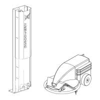
1 1 Construction of the charger unit............................................................................................ 1-1
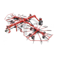
1 2 Construction of the Discovery barn cleaner.......................................................................... 1-2
2 1 Construction of the charger unit............................................................................................ 2-1
2 2 Positioning of the charger unit ..............................................................................................2-2
2 3 Installation dimensions ......................................................................................................... 2-3
2 4 barn cleaner at the charger unit............................................................................................ 2-5
2 5 Location of the charging strips..............................................................................................2-5
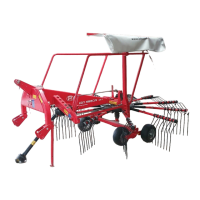
3 1 Discovery barn cleaning system ........................................................................................... 3-1
3 2 Barn cleaner (metal ring) ...................................................................................................... 3-2
3 3 Barn cleaner (manure scraper)............................................................................................. 3-2
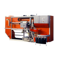
3 4 Charger unit (floor-mounted) ................................................................................................ 3-3
3 5 Battery charger LED ............................................................................................................. 3-3
3 6 E-link manual controller ........................................................................................................ 3-4
3 7 PCB connectors (multiboard ADS3800A)............................................................................. 3-8
4 1 Example route for barn cleaner ............................................................................................ 4-1
4 2 E-link manual controller ........................................................................................................ 4-2
4 3 "Work" flow diagram ............................................................................................................. 4-3
4 4 "Routes" flow diagram .......................................................................................................... 4-4
4 5 "Test" flow diagram............................................................................................................... 4-10
4 6 "Adjustments" flow diagram .................................................................................................. 4-13
4 7 "Alarms" flow diagram........................................................................................................... 4-14
4 8 "Service" flow diagram.......................................................................................................... 4-17
4 9 Left-handed circuit ................................................................................................................ 4-19
4 10 Right-handed circuit.............................................................................................................. 4-19
4 11 Route with a gradual curve................................................................................................... 4-19
4 12 Route with a tight curve ........................................................................................................ 4-19
4 13 Example route....................................................................................................................... 4-20