11
WARNING
Failure to rotate the HD Display before pulling it off of the Mag-Mount may loosen
the dry wall anchors or pull the Mag-Mount off of the wall due to the increased
forced required to separate the HD Display from the Mag-Mount when it is not
rotated.
NOTE: If the HD Display is removed from the Mag-Mount base, the HD Display will
shut down and not be able to communicate with the system. System can
be controlled from mobile devices or dealer web portal once registration
has been completed.
5. Do not remove the protective lm covering the HD Display screen until after
power is applied to the system.
CAUTION
1) Battery may need to charge before operation. Once the display
is connected, instructions may appear within 15 seconds with
further detail.
2) TO AVOID BREAKING THE GLASS DISPLAY
a. Do not apply force directly to the glass display
b. Holding the display horizontally
i. Center the display cavity on the base
ii. Press both sides equally until the snaps engage
3) AVOID EXCESSIVE FORCE TO THE CLASS DISPLAY
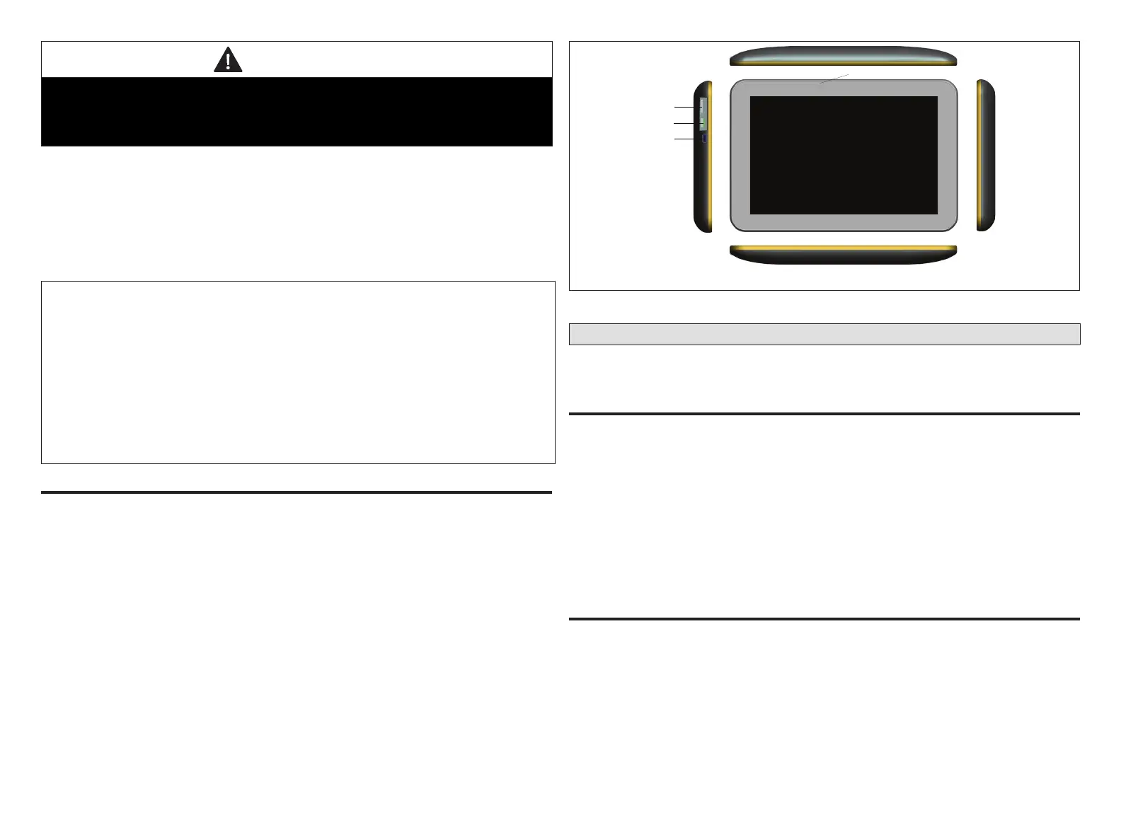
ExtErnal ComponEnts
• Proximity Sensor - Detects a person approaching the HD Display. If the HD
Display is in Screen Saver mode and the Proximity Detect feature is set to ON,
the proximity sensor takes the HD Display out of screen saver mode and returns
the home screen when someone approaches.
• Power Button - Resets the HD Display when pressed and held for about 5
seconds.
• microSD Card slot - Not functional, for future use
• Micro USB connector - Not functional, for future use
Proximity Sensor
Power Button
microSD Slot
Micro USB Connector
Figure 5. HD Display Components
Connecting Low Voltage Wiring
The following diagrams illustrate the basic Lennox communication control wiring
for all compatible components.
DisChargE air tEmpEraturE sEnsor (Dats)
Installation of discharge air temperature sensor (DATS) (88K38) must comply with
the following requirements:
• Installed downstream of the heat exchanger or electric heat elements.
• It must be placed in free airow, where other accessories (such as humidiers,
UV lights, etc.) will not interfere with its accuracy.
• Wiring distance between the Smart Hub and the discharge air sensor must not
exceed 10 feet (3 meters) when wired with 18 #AWG thermostat wire.
• DATS is highly recommended for all systems to provided more precise
dehumidication operation.
outDoor air tEmpEraturE sEnsor (oats)
The optional outdoor air (temperature) sensor (OATS) (X2658) wiring distance to
iComfort E30 should not exceed 150 feet (45 meters) when wired with minimum
22 #AWG (recommend 18 #AWG) dedicated 2-conductor thermostat cable.
Installation of OATS must comply with the following requirements:
• Sensor wiring must be run to avoid touching or being close to high voltage wiring
and light ballast.
• Choose a protected outdoor location away from direct sunlight or other heat
sources (usually on the north side of the building).

 Loading...