12
• Ensure that water will neither collect on, or wash over the sensor.
• Do not locate the sensor near driveways or similar heat-absorbing masses which
may reect stored heat energy onto the sensor and send inaccurate information
to the thermostat.
• Locate the sensor away from attic and soft vents, or furnace venting pipes.
• Do not locate the sensor directly above an air conditioner or heat pump.
Wiring spECiFiCations
The following is the wiring specication for the system:
• Smart Hub to Mag-Mount wiring size is 18 #AWG.
• Thermostat does not required shielded cable wiring.
• Maximum total length of all connections combined is 1500 feet (457 meters).
• Maximum length between components is 300 feet (90 meters).
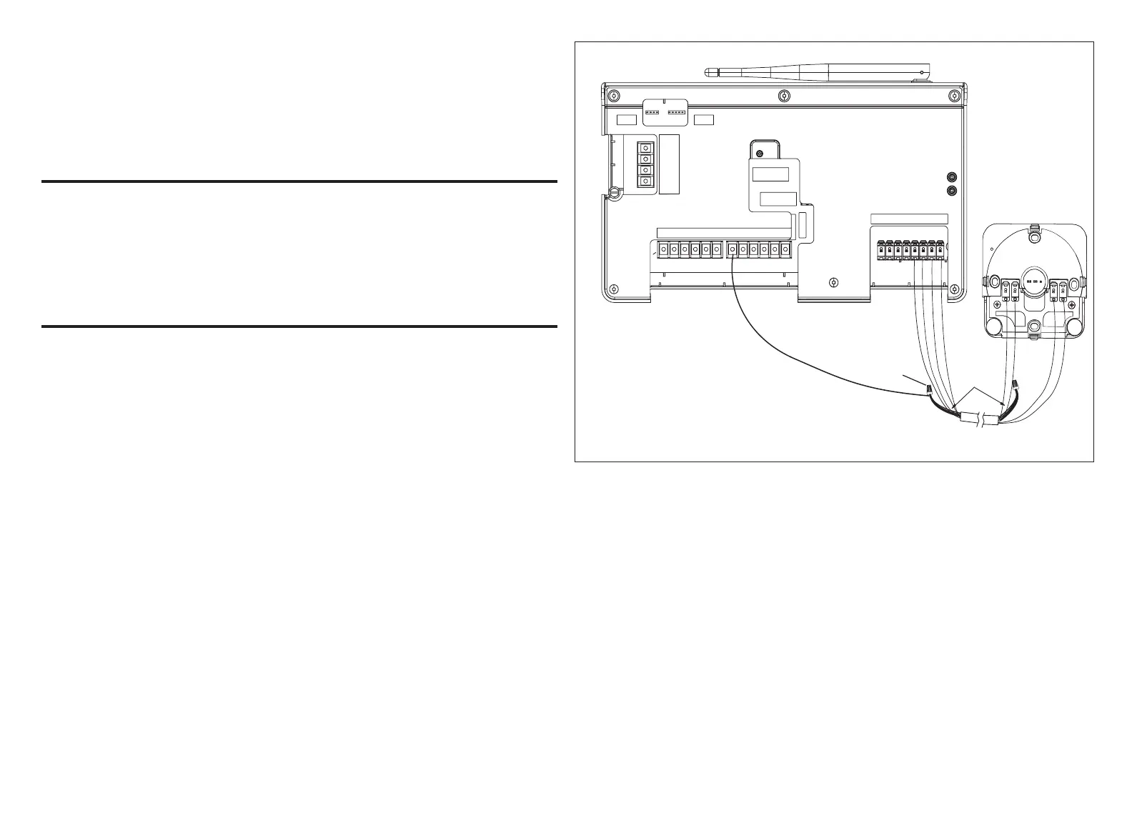
rEDuCing ElECtriCal noisE on CommuniCation Bus
This system requires four thermostat wires between the Mag-Mount and Smart
Hub.
When a thermostat cable with more than four wires is used, the extra wires
must be properly connected to avoid electrical noise. The wires must not be left
disconnected.
• Use wire nuts to bundle the unused wires at each end of the cable. A single
wire should then be connected to the indoor unit end of the wire bundle and
attached to the “C” terminals as shown in “Figure 6. Thermostat Wire Termination
(Electrical Noise)”.
• Keep all wiring as far away from the house electrical wiring and large electrical
appliances as possible. Recommended minimal distance is 15 feet (5 meters).
W1 W2 W3 GY2Y1
C
DS RHOB
UNIT
TYPE
HEAT
STAGES
OUTDOOR
AIR
SENSOR
DISCHARGE
AIR
SENSOR
HP
IFC
AHC
0 1 2 3
COMM
A
BUS
B
12VDC
+ -
ACC2ACC1
12VDC
+ -
COMM
A
BUS
B
Unused
wires
Single wire from bundle
to Smart Hub 24VAC
Terminal C
E30 SMART HUB
MAG-MOUNT
Figure 6. Thermostat Wire Termination (Electrical Noise)

 Loading...