8
Table 5. Heat Stage Jumpers
Label
(Position)
Air Handler Heat Stages Furnace Heat Stages Heat Pump Stages
Number of
Electric Heat
Stages
Stage
Percentage
Number of
Gas Stages
Stage
Percentage
Number of
Compressors
Stages
Stage
Percentage
0 No Electric Heat 0 1 100% 1 100%
1 1 100% 1 100% 1 100%
2
(default)
2 50%, 100% 2 70%, 100% 3 70%, 100%
3 3 33.5%, 66.5%, 100% 2 70%, 100% 3 70%, 100%
If jumper is missing, setting defaults to single stage. Changing jumper position after power-up requires recommission for the change to be recognized.
air tEmpEraturE sEnsor ConnECtions
Table 6. Sensors
Label Function / Description
Outdoor
Air Sensor
Show ambient temperatures (optional if weather feed is
acceptable; use X2658 Outdoor Sensor - 2 terminals).
Wiring distance between the thermostat and the outdoor
temperature sensor can not exceed 200 feet (61 m) when
wired with 18 #AWG thermostat wire.
Discharge
Air Sensor
Optional for diagnostics of indoor air; use 88K38 Discharge
Air Sensor - 2 terminals.
Wiring distance between the furnace or air handler control
module and the discharge air sensor should not exceed 10
feet (3 meters) when wired with 18 #AWG thermostat wire.
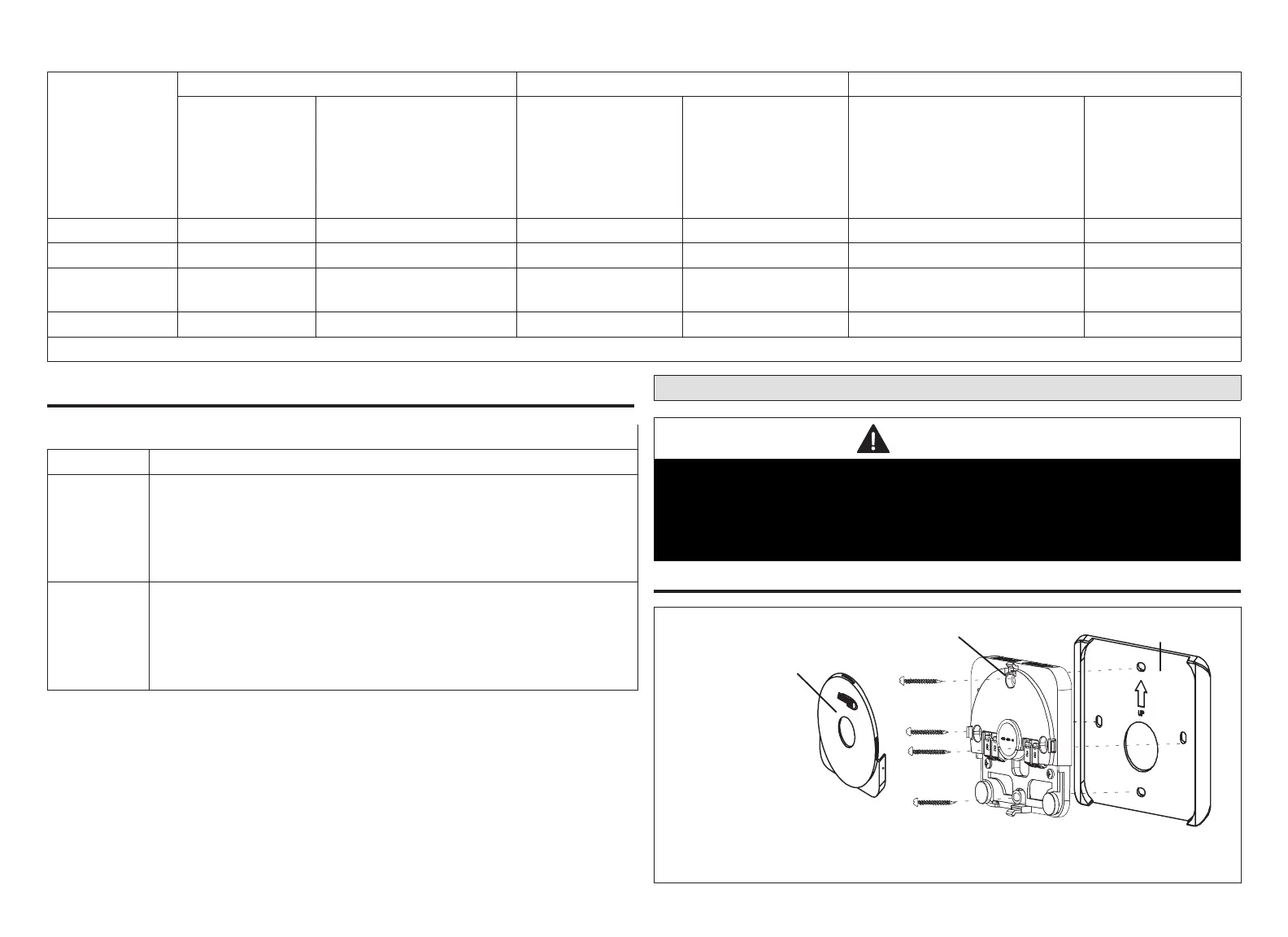
Mag-Mount LED and Installation
CAUTION
Magnets located in this product have far-reaching and strong magnetic elds.
They could damage TVs and laptops, computer hard drives, credit and ATM
cards, data storage media, mechanical watches, hearing aids and speakers.
Keep HD Display and Mag-Mount away from devices and objects that could be
damaged by strong magnetic elds.
installation
OPTIONAL)
MAG-MOUNT WITHOUT
ACCESS COVER
ACCESS
COVER
WHEN REINSTALLING
CCESS COVER MAKE SURE THAT IT
IS SEATED PROPERLY. NOT DOING
SO WILL CAUSE CONNECTION
ISSUES.

 Loading...