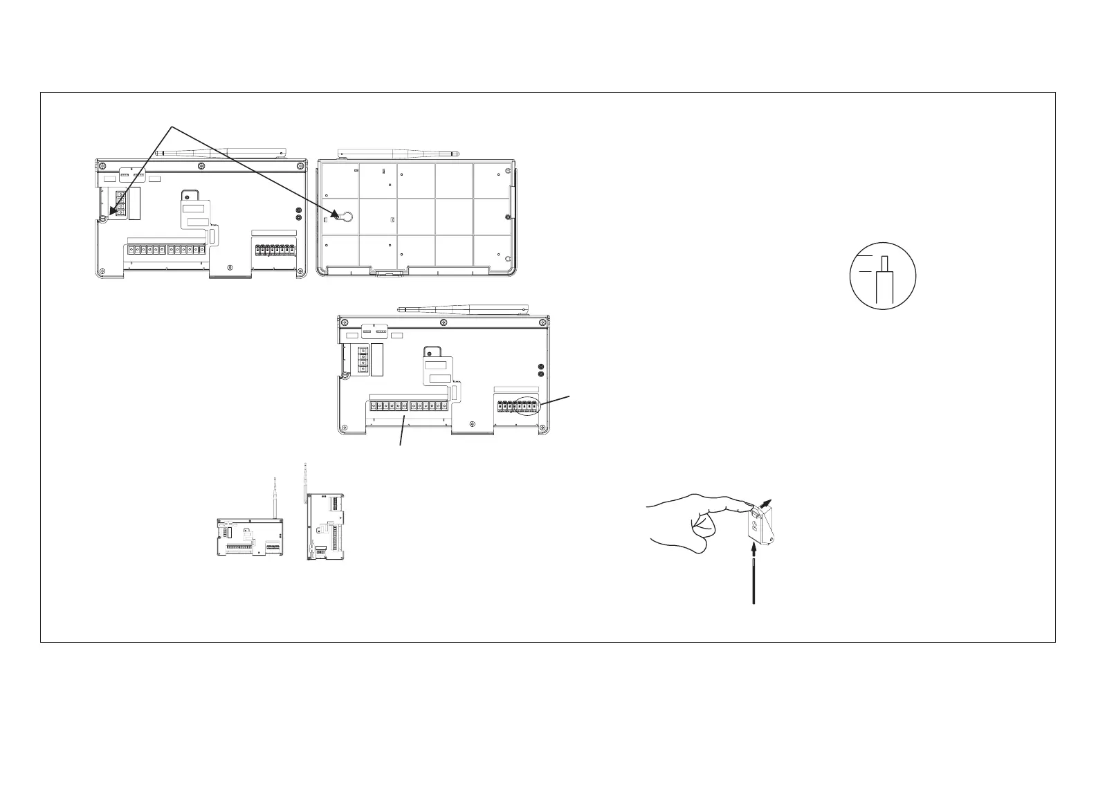
2. Use the following procedure outlined in “Figure 1. Smart Hub Installation” to install the Smart Hub.
3. For low voltage wiring connections use diagrams in section titled “Connecting Low Voltage Wiring” on page 11.
1/4”
A
B
D
W1 W2 W3 GY2Y1
C
DS RHOB
UNIT
TYPE
HEAT
STAGES
OUTDOOR
AIR
SENSOR
DISCHARGE
AIR
SENSOR
HP
IFC
AHC
0 1 2 3
COMM
A
BUS
B
12VDC
+ -
ACC2ACC1
Front
(Hinged Cover Removed)
Rear
Keyhole
Use the Smart Hub as a template to mark the desired mounting locations on the wall or stud.
CAUTION: Do not overtighten lower mounting
screw. Doing so may damage the Smart Hub.
Secure Smart Hub to
wall using field-provided
fasteners.
Strip 1/4” insulation from
end of each control wire.
18 #AWG Thermostat Wire
Make connections to the Smart Hub using included wiring
diagrams in this instruction.
Push spring-loaded lever in and insert wire
through hole located on bottom side of connector.
Release lever to secure wire.
Smart Hub to Mag-Mount
Connectors
W1 W2 W3 GY2Y1
C
DS RHOB
UNIT
TYPE
HEAT
STAGES
OUTDOOR
AIR
SENSOR
DISCHARGE
AIR
SENSOR
HP
IFC
AHC
0 1 2 3
COMM
A
BUS
B
12VDC
+ -
ACC2ACC1
W1W2 W3 GY2Y1
C
DS RHOB
UNIT
TYPE
HEAT
STAGES
OUTDOOR
AIR
SENSOR
DISCHARGE
AIR
SENSOR
H
P
IFC
AHC
0 1 2 3
COMM
A
BUS
B
12VDC
+ -
ACC2ACC1
W1W2 W3 GY2Y1
C
DS RHOB
UNIT
TYPE
HEAT
STAGES
OUTDOOR
AIR
SENSOR
DISCHARGE
AIR
SENSOR
HP
IFC
AHC
0 1 2 3
COMM
A
BUS
B
12VDC
+ -
ACC2ACC1
Smart Hub may be installed either horizontally or
vertically as illustrated.
Smart Hub illustrated with
hinged cover removed.
24VAC Equipment Connections
C
Figure 1. Smart Hub Installation

 Loading...