Server models with twenty 2.5-inch drives
Use this section to understand the cable routing for server models with twenty 2.5-inch drives.
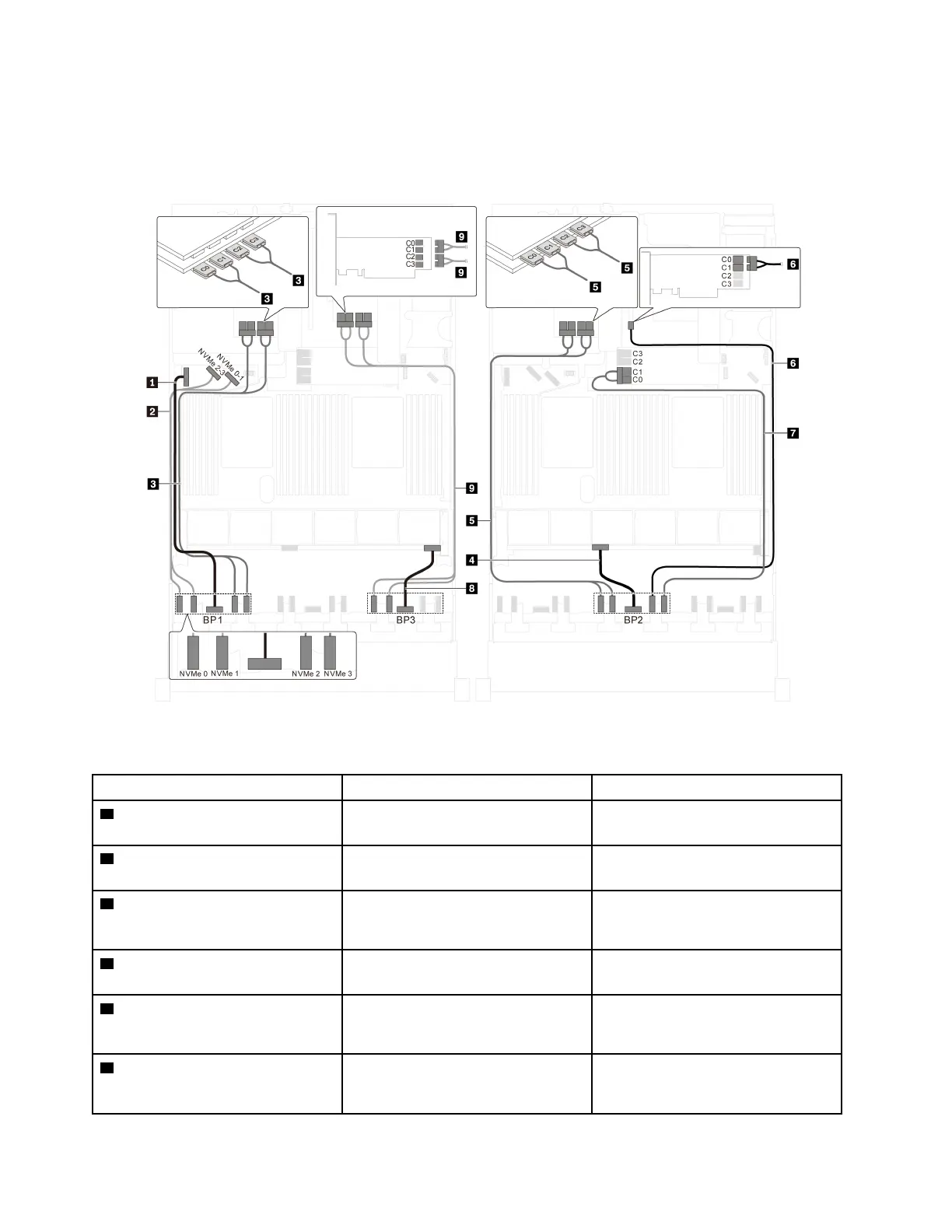
Server model: twenty 2.5-inch NVMe drives, two NVMe 810-4P switch adapters, three NVMe 1610-4P
switch adapters
Figure 43. Cable routing for server models with twenty 2.5-inch NVMe drives, two NVMe 810-4P switch adapters, and
three NVMe 1610-4P switch adapters
Cable From To
1 Power cable for front backplane 1 Power connector on front backplane
1
Backplane power connector 1 on the
system board
2 NVMe signal cable for front
backplane 1
NVMe 0 and NVMe 1 connectors on
front backplane 1
NVMe 2–3 and NVMe 0–1 connectors
on the system board
3 NVMe signal cable for front
backplane 1
NVMe 2 and NVMe 3 connectors on
front backplane 1
C0, C1, C2, and C3 connectors on
the NVMe 1610-4P switch adapter
installed in PCIe slot 6
4 Power cable for front backplane 2 Power connector on front backplane
2
Backplane power connector 2 on the
system board
5 NVMe signal cable for front
backplane 2
NVMe 0 and NVMe 1 connectors on
front backplane 2
C0, C1, C2, and C3 connectors on
the NVMe 1610-4P switch adapter
installed in PCIe slot 5
6 NVMe signal cable for front
backplane 2
NVMe 2 connector on front
backplane 2
C0 and C1 connectors on the NVMe
810-4P switch adapter installed in
PCIe slot 4
72 ThinkSystem SR650 Setup Guide

 Loading...


