Electrical installation
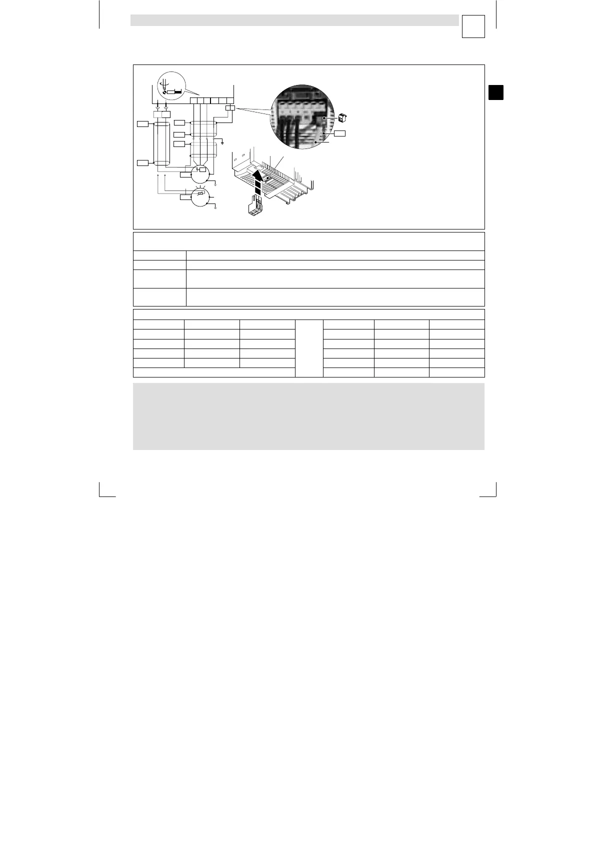
Connection of motor / brake resistor
4
EDK82EV113 DE/EN/FR 8.1
105
L
U
PES
V W
BR2
PE
PE
PE
PES
PES
PES
PES
T1 T2
M
3~
ϑ>
PES
PES
M
3~
PTC
8200 vector
X2.2
X2.1
X2.1
P
E
W
B
r2
U
B
r1
V
T
2
T
1
X2.2
BR1
PE
0,7...0,8 Nm
6.2...7.1 lb-in
6mm/0.24in
}
PES
PE
−24−8200vec064
Use low−capacity motor cables! (core/core up to 1.5 mm
2
75 pF/m; from 2.5 mm
2
100 pF/m; core/shield 150 pF/m)
The shorter the motor cables, the better the drive response!
PES HF−shield end by PE connection through shield bracket or EMC cable connection.
X2.1/PE Earthing of the 8200 vector at the output side
X2.1/BR1,
X2.1/BR2
Connection terminals for the brake resistor
(For information about the operation with brake resistor see the Operating Instructions)
X2.2/T1, X2.2/T2 Connection terminals motor temperature monitoring through PTC thermistors or thermal contacts
Activate motor temperature monitoring under C0119 (e. g. C0119 = 1)!
Cable cross−sections U, V, W, PE
Type mm
2
AWG Type mm
2
AWG
E82EV302K2C 2.5 12 E82EV302K4C 1 16
E82EV402K2C 4 10 E82EV402K4C 1.5 14
E82EV552K2C 6 10 E82EV552K4C 2.5 12
E82EV752K2C 6 10 E82EV752K4C 4 10
E82EV113K4C 4 10
Danger!
l After the connection of a PTC thermistor or thermal contact all control
terminals only have a basic insulation (single insulating distance).
l Protection against contact in the event of a defective insulating distance
can only be ensured by external measures (e.g. double insulation).
Artisan Technology Group - Quality Instrumentation ... Guaranteed | (888) 88-SOURCE | www.artisantg.com