Changing the assignment of the control terminals X5 and X6
Free configuration of analog outputs
6.5
6.5.4
6.5−6
EDSVF9383V EN 7.1−04/2012
6.5.4 Free configuration of analog outputs
ƒ The analog outputs (X6/62, X6/63) can be freely linked with internal
analog process or monitoring signals. The controller outputs a voltage
proportional to the internal signal at the analog outputs.
ƒ One signal source can be linked with several targets.
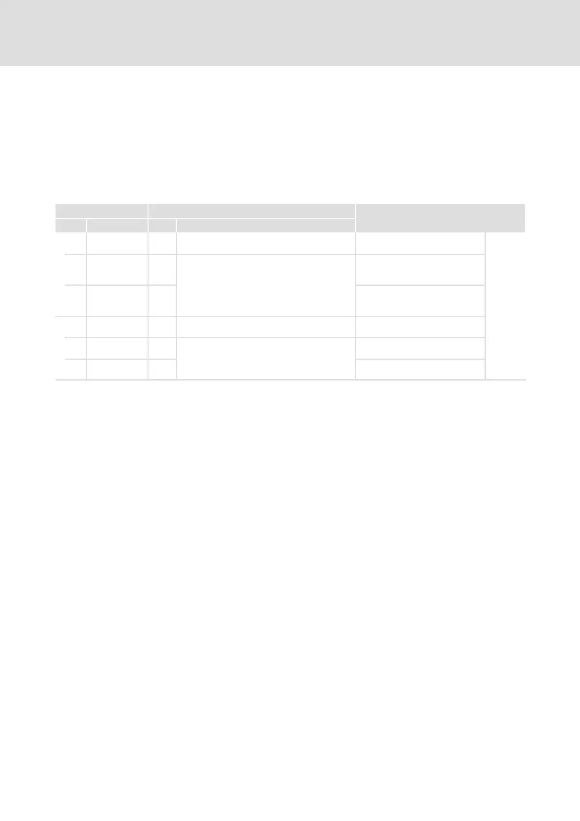
Codes for parameter setting
Code Possible settings IMPORTANT
No. Name Lenze Selection
C0108 −199.99 {0.01 %} 199.99 Free control code FCODE108/1
and FCODE108/2
6.5−6
See System
Manual
(extension)
1 FCODE (gain) 100.0
0
Gain of analog output signal
AOUT1 (X6/62)
l 100 % = gain 1
2 FCODE (gain) 100.0
0
Gain of analog output signal
AOUT2 (X6/63)
l 100 % = gain 1
C0109 −199.99 {0.01 %} 199.99 Free control code FCODE109/1
and FCODE109/2
1 FCODE (offset) 0.00 Offset of analog output signal
AOUT1 (X6/62)
2 FCODE (offset) 0.00 Offset of analog output signal
AOUT2 (X6/63)
Analog outputs can be linked with internal analog signals by entering the
selection figure of the internal signal into the code of C0431 (AOUT1, X6/62)
or C0436 (AOUT2, X6/63).
Example
ƒ C0436 = 5006 ð signal source for X6/63 is the actual motor voltage
Tip!
ƒ A list with all selection figures is included in the chapter
"Configuration" ® "Selection lists".
ƒ For signal linkage we recommend the function block editor in
GDC (ESP−GDC2).
Set gain (C0108) and offset (C0109) to adapt the output signal to the
application.
With an internal signal of 100 % and a gain of 1, a voltage of 10 V is output
at the terminal.
Description
Linking signals
Adjustment

 Loading...


