Basic devices in the power range 250 ... 400 kW
DC supply 400/500 V devices
5.5
5.5.5
5.5−8
EDSVF9383V EN 7.1−04/2012
5.5.5 DC supply 400/500 V devices
Stop!
The user is responsible for sufficient strain relief!
ƒ For compliance with EMC requirements, Lenze recommends to use
shielded DC−bus cables.
ƒ Shield clamps are not included in the scope of supply.
ƒ Both, the master and the slave must be supplied!
BR2 BR2BR1 BR1+UG +UG-UG -UG
PE PE
U U
V VW W
L1 L1
101
101
102
102
103
103
104
104
L2 L2
L3 L3
PE PE
40mm 40mm
PE
15-20
Nm
M6
133-176 lb-in
PE
15-20 Nm
M6
133-176 lb-in
+U
G
+U
G
-U
G
-U
G
25-30 Nm 25-30 Nm
M8 M8
221-264 lb-in 221-264 lb-in
max.
300 mm
max.
300 mm
33
22
0
1
9300VEC083
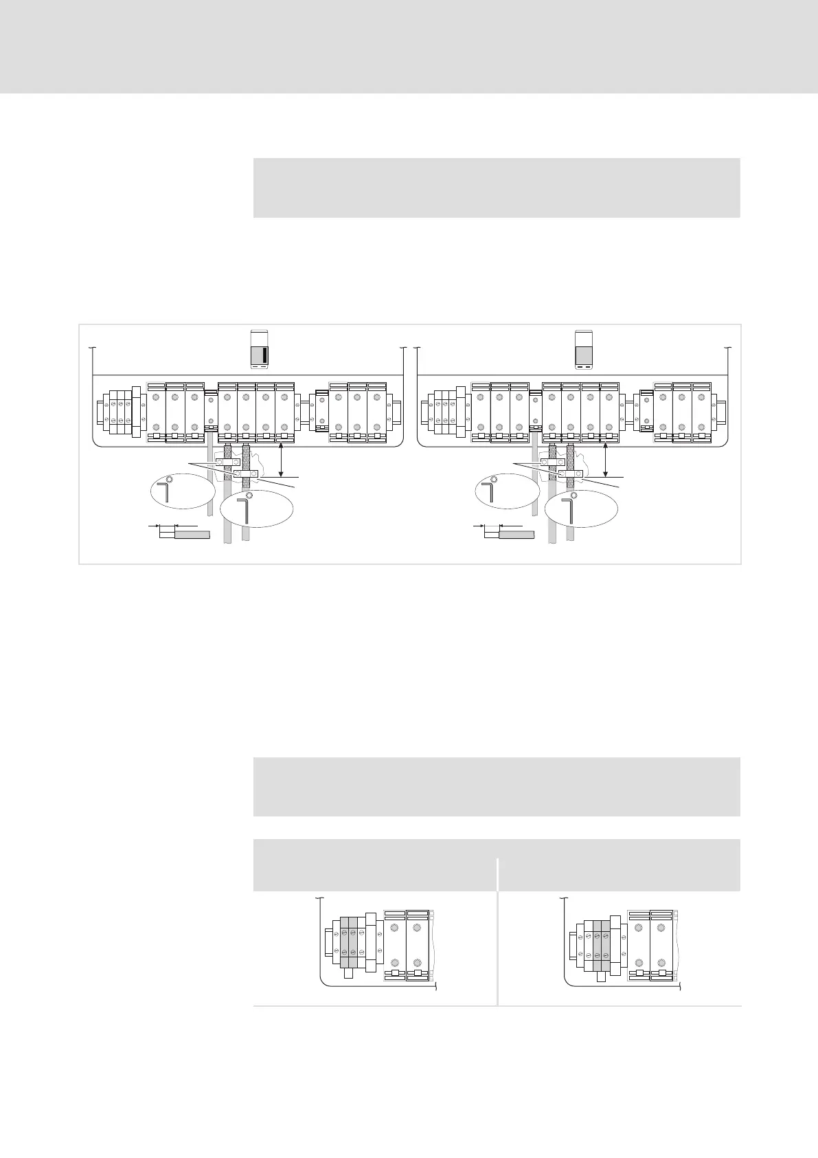
Fig. 5.5−9 Connection example to +U
G
and −U
G
BR1, BR2 Brake resistors can only be operated with variants V270 and V300
Master terminals
Slave terminals
Connect the DC−bus cable shield to the conductive control cabinet
mounting plate with a contact surface as large as possible by using
the shield clamps.
Conductive surface
Ensure to have the poles right!
5.5.6 Fan connection 400/500 V devices
Note!
Connect the fan to the master and the slave.
Lay a bridge between the terminals when a controller is operated on a mains.
AC 340 ... 440 V AC 440 ... 577 V
(when being delivered)
L1 L2
101
102
103
104
101
102
103
104
L1 L2
9300vec044 9300vec045
Fan connection when
controller is supplied with
mains voltage

 Loading...


