10 Lenze EDBZAEDE1001 DE/EN/FR/ES/IT 1.0
3.2 LED Operation
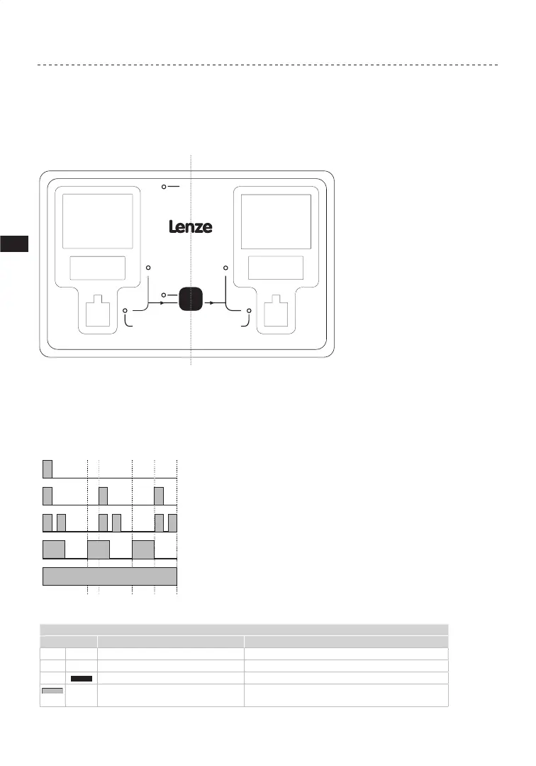
Figure 6 illustrates the LEDs located on the front panel of the Memory Module Copier. The
gray text is not on the actual product.
Memory Module Copier
SLAVEMASTER
POWER
COPY
840
tate/High/Toplin
400
State/High/Toplin
Lenze
C Tec
E
Lenze
C Tec
EP
Figure 6: LED Locations
In the tables that follow, gray bars or circles represent the red LED and black bars or circles
represent the green LED.
A circle with no fill represents an LED that is OFF (not illuminated m m).
LED flashes 1x every 3s (slow flash)
LED flashes 1x every 1.25s (flash)
LED flashes 2x ever
LED flashes 1x every 1s
LED is permanently ON
1.25 2.50
COPY LED
STATE LED Description State Description
Red Green
m m
Both Off No [COPY] push-button (PB) action
m
Red: Off; Green: On Copying in progress
m
Red: On (while PB pressed); Green: Off If red when [COPY] is pressed, no Master/Slave sockets
are ready for operation