5 Installation
5.3 Activating the bus terminating resistor
29
Lenze · E84AYCPM communication module (PROFIBUS®) · Communication Manual · DMS 5.0 EN · 11/2012 · TD17
_ _ _ _ _ _ _ _ _ _ _ _ _ _ _ _ _ _ _ _ _ _ _ _ _ _ _ _ _ _ _ _ _ _ _ _ _ _ _ _ _ _ _ _ _ _ _ _ _ _ _ _ _ _ _ _ _ _ _ _ _ _ _ _
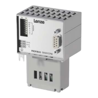
5.3.2 PROFIBUS connection
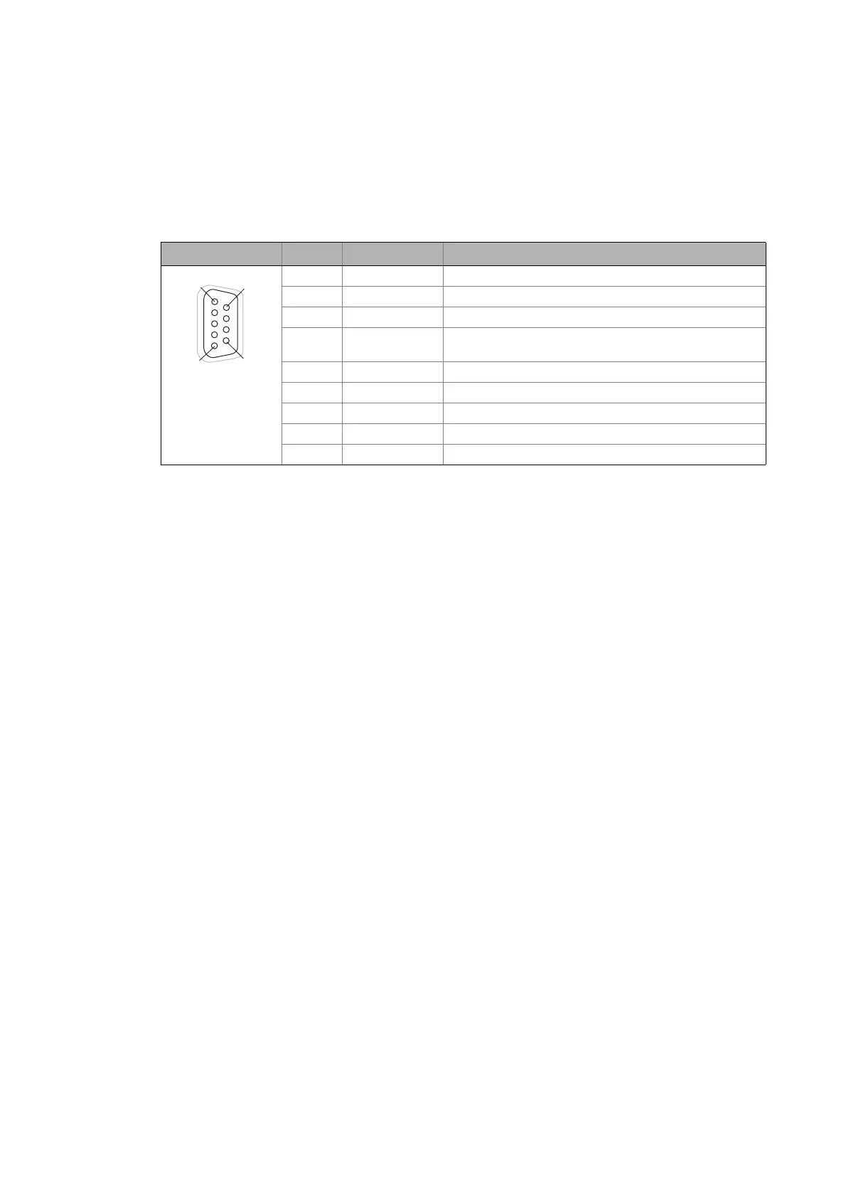
The 9-pole Sub-D socket X201 serves to connect the communication module to the bus system.
Assignment of the 9-pin Sub-D socket X201
View Pin Assignment Description
1Not assigned-
2Not assigned-
3 RxD/TxD-P Data line B (received data/transmitted data, plus)
4 RTS Request To Send (received data/transmitted data, no
differential signal)
5 M5V2 Data ground (ground to 5 V)
6 P5V2 5 V DC / 30 mA (bus termination)
7Not assigned-
8 RxD/TxD-N Data line A (received data/transmitted data, minus)
9Not assigned-
1
6
5
9