Lenze · E84AYCPM communication module (PROFIBUS®) · Communication Manual · DMS 5.0 EN · 11/2012 · TD17 32
6 Commissioning
6.3 Setting the station address
_ _ _ _ _ _ _ _ _ _ _ _ _ _ _ _ _ _ _ _ _ _ _ _ _ _ _ _ _ _ _ _ _ _ _ _ _ _ _ _ _ _ _ _ _ _ _ _ _ _ _ _ _ _ _ _ _ _ _ _ _ _ _ _
6.3 Setting the station address
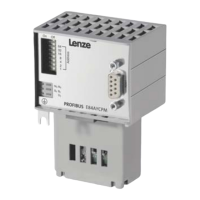
[6-1] DIP switch
The station addresses must differ from each other if several networked PROFIBUS stations are used.
The station address can be set via DIP switches 1 ... 64 or via the »Engineer« (code C13899
).
The housing labelling indicates the valencies of the individual DIP switches for setting the station
address.
• Valid address range: 1 … 126 (max. 126 slave stations)
• C13920
: Display of the current address setting of the switches
• C13864
: Display of the station address active on the PROFIBUS
E84YCPM001G
The station address can be set via DIP switches 1 ... 64 or via the
»Engineer« (code C13899
).
The unlabelled DIP switch (topmost position) does not have any
function.
Lenze setting: all switches in OFF position
Setting the station address via ...
DIP switch C13899
Condition At least one switch 1…64=ON •Switches 1...64=OFF
• All switches 1...64=ON
(invalid value "127")
DIP switch 64 32 16 8 4 2 1
Switch position OFF OFF ON OFF ON ON ON
Value 00
16 0 4 2 1
Station address = sum of the valencies = 16 + 4 + 2 + 1 = 23
DIP switch positions for setting the station address ( 107)
Note!
Switch off the voltage supply of the communication module and then on again in order
to activate changed settings.