33
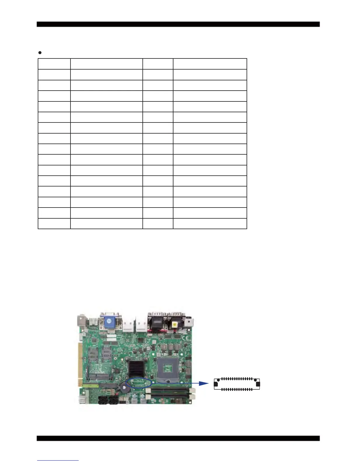
LVDS1: LVDS interface (2x15 pin 1.25mm wafer)
PIN NO. Description PIN NO. Description
1 PWM dimming 2 +5V
3 +LCD(5V or 3.3V) 4 +LCD(5V or 3.3V)
5 Channel-1-DATA3+ 6 Channel-0-DATA3+
7 Channel-1-DATA3- 8 Channel-0-DATA3-
9 Channel-0-DATA2+ 10 Channel-0-CLK+
11 Channel-0-DATA2- 12 Channel-0-CLK-
13 GND 14 GND
15 Channel-0-DATA1+ 16 Channel-0-DATA0+
17 Channel-0-DATA1- 18 Channel-0-DATA0-
19 GND 20 GND
21 +LCD(5V or 3.3V) 22 +LCD(5V or 3.3V)
23 Channel-1-DATA2+ 24 Channel-1-CLK+
25 Channel-1-DATA2- 26 Channel-1-CLK-
27 Channel-1-DATA1+ 28 Channel-1-DATA0+
29 Channel-1-DATA1- 30 Channel-1-DATA0-
Note: 1. LVDS interface support 18/24bits two channel
2. JVL1: LVDS panel +5V/+3.3V Voltage select
3. LVDS1 PIN 1 for panel backlight active, Default active setup by DPC Control
4. Pin 1 back light dimming control. Provided 200Hz / 275Hz / 380Hz / 20KHz / 25KHz
And adjust PWM duty cycle by software program
5. Mating connector: HIROSE DF13-30DS-1.25C or compatible
6. Cable housing: HIROSE DF13-30DP-1.25V or compatible
LVDS1
pin1
30
3-8 LVDS interface