30
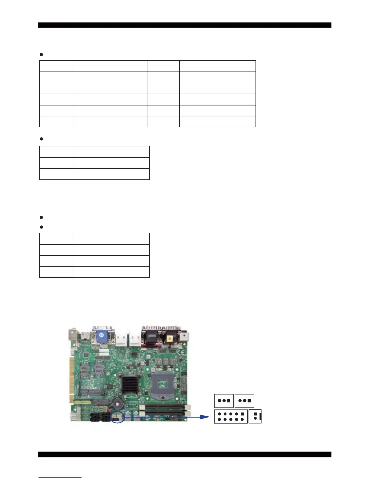
3-5 Front panel & FAN
CFP1 Front panel connector (2 X 5 pin 2.54mm wafer)
PIN NO. Description PIN NO. Description
1 Power button pin 2 Power button GND
3 Reset pin 4 Reset GND
5 Power LED - 6 Power LED +
7 HDD LED- 8 HDD LED+
9 LAN LED- 10 LAN LED+
FAN1: CPU FAN connector (3pin 2.5mm wafer)
FAN2: System FAN connector (3pin 2.5mm wafer)
SWP1 PB connector (2pin 2.0mm wafer)
FAN connectors
PIN NO. Description
1 GND
2 +12V
3 FAN speed detect
PIN NO. Description
1 Power button pin
2 Power button GND
Note: DC in +12V by switch to FAN power +12V,
so DC in need stable +12V input
CFP1
SWP1
FAN1
FAN2
pin1
pin1
10