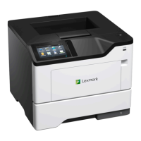
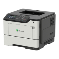
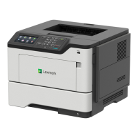
MS510/MS610 rollers
Duplex rear
deliver roller
Transfer roll
First input roller
Photoconductor
drum
Paper exit roller
Fuser exit
roller
Secondary input
roller
Duplex front
deliver roller
Separator roll
Pick rollers
Separator roll
Pick rollers
Fuser assembly
Electrophotographic process (EP process)
Printhead
The printhead scans the photo conductor drum surface with a laser beam. It consists of the following components:
• Laser diode (LD) card assembly
• Oscillator
• Start of scan card assembly
When a laser beam is scanned across the photoconductor drum surface from one end to the other while turning on
and off the beam, one line of latent image is created. If the scanning by the laser beam is repeated while rotating the
drum, a two-dimensional image is created. The resolution in the scanning direction (from right to left) is determined
by the rotational speed of the printhead motor, depending on how quickly the laser is adjusted. The resolution in the
process direction (from top to bottom) is determined by the rotational speed of the printhead motor. The higher the
scanning speed becomes, the sooner the scanning of the next row can be started.
4514-630, -635, -636
Appendix C: Theory of operation
291

 Loading...