iPECS-MG Hardware Description and Installation Manual Issue 1.1
DECT INSTALLATION August, 2010
30
Referring to Figure 5.2.5-1 and the pin-out chart below
wire the Alarm Tip and Alarm Ring located on pins 2 and 3 of the RJ-11 to the Alarm contact
termination point using UTP cable
wire the External Control Contact located at pins 4 and 5 of the RJ-11 to the external device using
UTP cable
tag or number wiring for maintenance
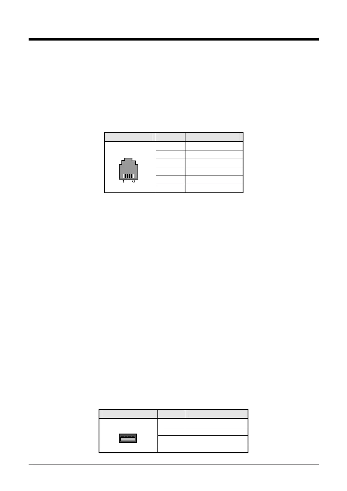
Alarm and Relay Contact Connector
CONNECTOR PIN SIGNAL NAME
1 Not used
2 ALARM-T
3 ALARM-R
4 Relay-T
5 Relay-R
RJ11
6 Not used
5.2.5.2 Page Audio Connector Wiring
The Page connector allows paging audio to be sent to External Paging equipment. The system will
deliver audio as a 0-dBm signal into a 600-ohm load.
Referring to Figure 5.2.5-1,
wire the Page Audio connector to the termination point of the audio input of the External Page
equipment
tag or number wiring for maintenance
5.2.5.3 MOH Connector Wiring
When a call is placed on hold, MOH (Music on Hold) is presented to the caller. MOH can be provided
from an internal source or from an external audio source connected to the MOH connector.
Referring to Figure 5.2.5-1,
wire the MOH connector to the termination point of the audio output of the external MOH source
tag or number wiring for maintenance
5.2.6 USB Connector
The USB connector is provided to allow a USB memory stick to connect to the system for upload and
download of the System database. No wiring of the USB connector is required. For further
information on operation of the USB port, refer to the iPECS-MG Admin Manual.
USB Connector
CONNECTOR PIN SIGNAL NAME
1 GND
2 D+
3 D-
USB Type A
4 VBUS (+5V)