iPECS-MG Hardware Description and Installation Manual Issue 1.1
DECT INSTALLATION August, 2010
49
5.4.2.2 SLIBC Installation
The SLIB has no switches or connectors that are field useable. The SLIB can be installed in any
universal slot of any KSU; the 1
st
slot of the BKSU is for the MPB only. Note a maximum of four (4)
DTIB24/SLIB24Cs can be installed in a KSU.
Assure Power is OFF
Slide the SLIBC in the guide rails of the desired slot.
Tighten thumbscrews to hold the board firmly in place.
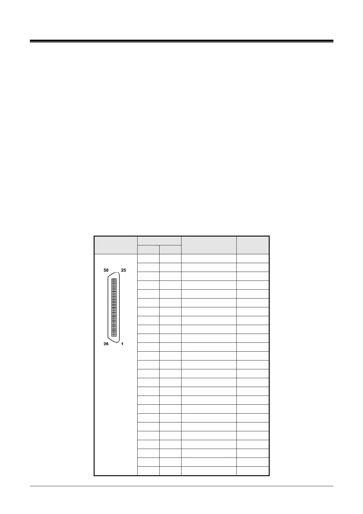
5.4.2.3 SLIBC Wiring
Each SLT port is terminated to a pair in the RJ21 connector. SLT 1 is terminated at pair 1, SLT 2 is
terminated on pair 2, etc. to the number of ports (12 or 24) on the SLIBC.
Referring to the pin-out chart below,
wire each SLT pair on the RJ-21 connector to the SLT termination point using UTP cable. The
maximum total wire length is 7500M/24Kft of 22 AWG wire or 5000M/16Kft of 24 AWG wire. For
information on wiring the SLT, refer to section 6.1.2.2
tag or number wiring for maintenance.
SLIBC Pin-Out Chart
PIN CONNECTOR
VT VR
COLOR CODE SLIB
PORT
1 26 1
2 27 2
3 28 3
4 29 4
5 30 5
6 31 6
7 32 7
8 33 8
9 34 9
10 35 10
11 36 11
12 37 12
13 38 13
14 39 14
15 40 15
16 41 16
17 42 17
18 43 18
19 44 19
20 45 20
21 46 21
22 47 22
23 48 23
24 49 24
RJ21
25 50