iPECS-MG Hardware Description and Installation Manual Issue 1.1
DECT INSTALLATION August, 2010
43
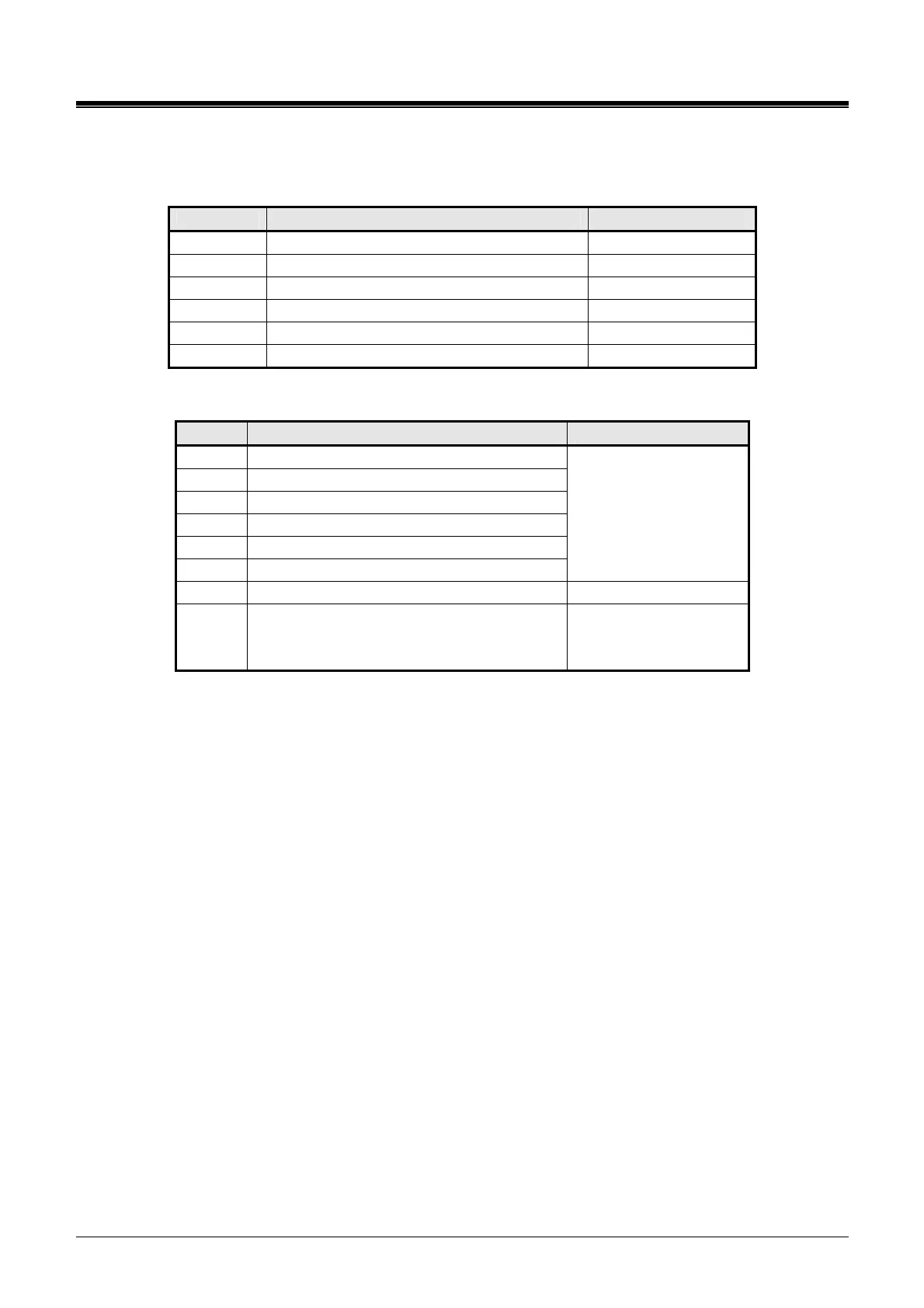
5.3.4.1 Switch and LED Functions
Switch Functions
SWITCH FUNCTION REMARK
SW1 Mode Selection (OFF = PRI, ON = T1) Default: PRI mode
SW3 Reset switch
SW4-1 Not used
SW4-2 Not used
SW4-3 Not used
SW4-4 Not used
LED Indication
LED FUNCTION REMARK
PLL PLL Synchronization
RDE Red Alarm Indication)
AIS Alarm Indication Signal/Blue Alarm
YAI Yellow Alarm Indication
MFE Multi-frame Establish Alarm
OOF Out of Frame
Red LED
ON = Error
OFF = Normal)
ACT Activity Indication Blue (Blink)
IN USE Indication of channel use
Blue LED
ON: Channels in use,
OFF: All channels idle
5.3.4.2 T1-PRIB Installation
Before inserting the T1-PRIB, set SW1 and SW4 Dip switches to match the Telco provided service.
Note that the PRIB supports ESF (Extended Super Frame) framing and B8ZS (Binary 8 Zero
Substitution) line coding only. The T1-PRIB board can be installed in any universal slot of any KSU;
the 1
st
slot of the BKSU is for the MPB only.
Assure Power is OFF.
Slide the PRIB in the guide rails of the desired slot.
Tighten thumbscrews to hold the board firmly in place.
5.3.4.3 T1-PRIB Wiring
The T1-PRIB Transmit and Receive pairs are terminated in the PRI/T1 RJ-45 connector. A single RJ-
45 is provided for the digital line interface.
Before wiring the PRIB, the Ferrite core provided with the T1-PRIB must be installed to reduce EMI
(Elector-Magnetic Interference). To install the Ferrite core,
open the core.
insert and loop the RJ45 terminated cable for the T1-PRIB through the core as shown in Figure
5.3.4-1.
close the Ferrite core over the cable.