iPECS-MG Hardware Description and Installation Manual Issue 1.1
DECT INSTALLATION August, 2010
40
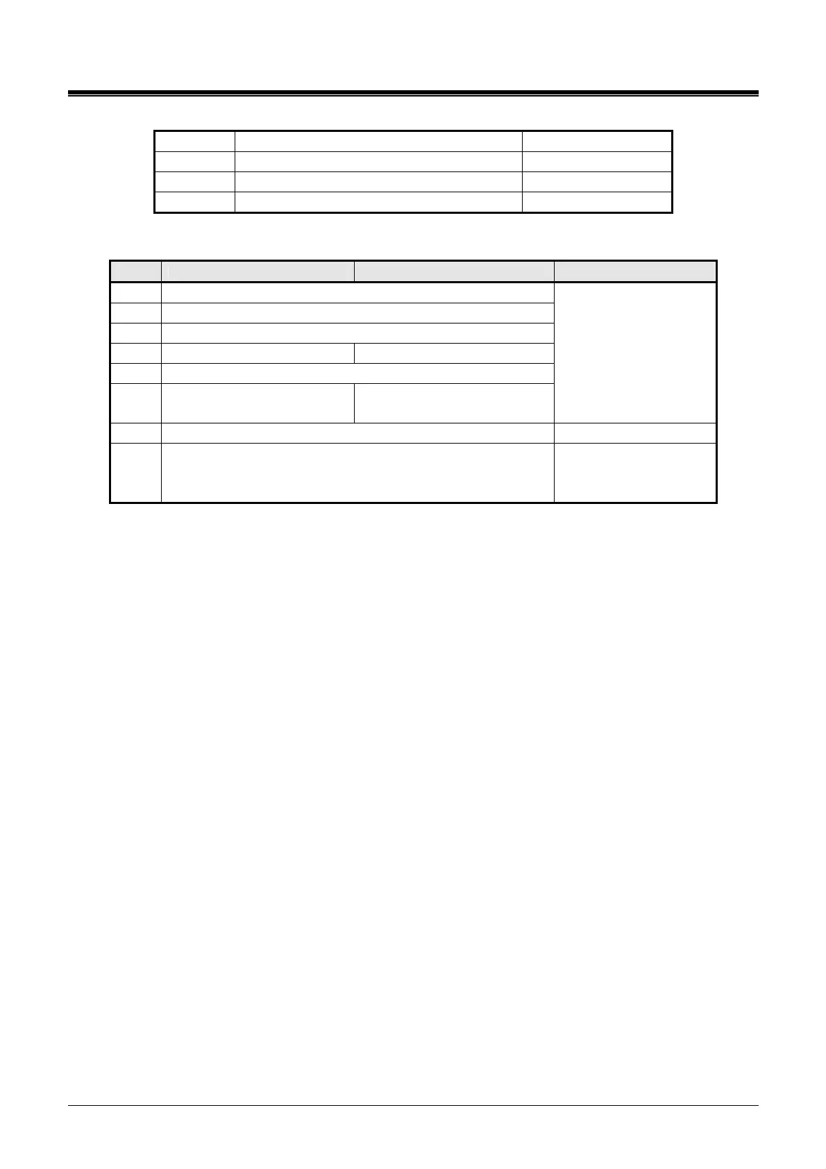
SW4-1 Not used
SW4-2 Not used
SW4-3 Not used
SW4-4 Not used
LED Indication
LED PRI MODE E1R2 MODE REMARK
LD1 PLL Synchronization
LD2 Loss of Signal from the Line
LD3 Alarm Indication Signal
LD4 Remote Alarm Indication Frame Alignment Error
LD5 Multi Frame Error
LD6 CRC Error
CRC
(ON : Enable, OFF : Disable)
RED LED
ON: Error
OFF: Normal operation
LD7 Normal operation indication (Activity Indication) Blue (Blink)
LD8 Channel status
Blue LED
ON: Channels in use
OFF: All channels Idle)
5.3.3.2 E1-PRIB Installation
Before inserting the PRIB, set SW1 and SW4 Dip switches to match the Telco provided service. The
PRIB board can be installed in any universal slot of any KSU; the 1
st
slot of the BKSU is for the MPB
only.
Assure Power is OFF
Slide the PRIB in the guide rails of the desired slot.
Tighten thumbscrews to hold the board firmly in place.
5.3.3.3 E1-PRIB Wiring
The E1-PRIB Transmit and Receive pairs are terminated in the PRI/E1 RJ-45 connector. A single
RJ-45 is provided for the digital line interface.
Before wiring the PRIB, the Ferrite core provided with the E1-PRIB must be installed to reduce EMI
(Elector-Magnetic Interference). To install the Ferrite core,
open the core,
insert and loop the RJ45 terminated cable for the E1-PRIB through the core as shown in Figure
5.3.3-1.
close the Ferrite core over the cable.
Referring to the pin-out chart and Figure 5.3.3.3-1 E1-PRIB Connector Wiring Diagram below,
wire the TX and RX pins of the RJ-45 connector to the digital line termination point using UTP cable.
tag or number wiring for maintenance.