iPECS-MG Hardware Description and Installation Manual Issue 1.1
DECT INSTALLATION August, 2010
32
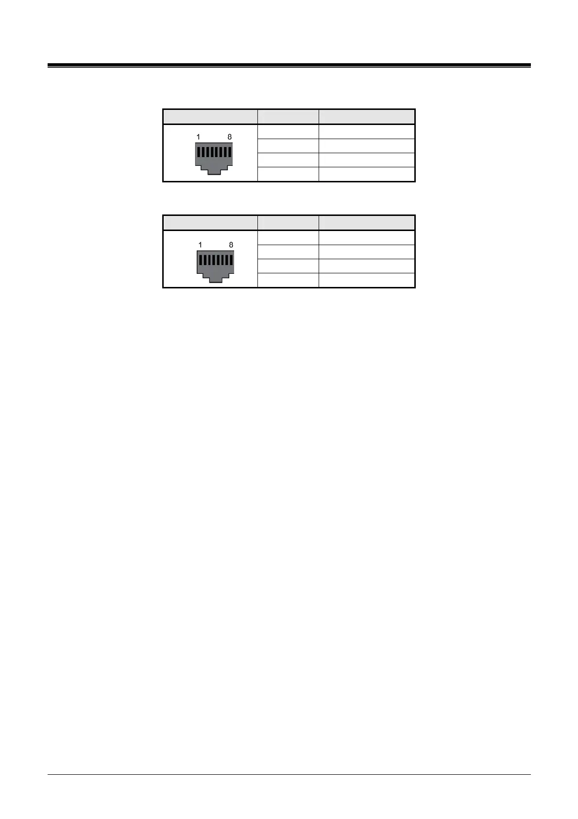
RJ45 Pin Assignment, DKT1 to 6 Connectors
CONNECTOR PIN SIGNAL NAME
1,2,3 Not used
4 DKT-T
5 DKT-R
RJ45
6,7,8 Not used
RJ45 Pin Assignment, SLT1 to 6 Connectors
CONNECTOR PIN SIGNAL NAME
1,2,3 Not used
4 SLT-T
5 SLT-R
RJ45
6,7,8 Not used
Referring to the pin-out charts above,
wire the DKT and SLT ports of the DSIU to the termination point of the appropriate DKT or SLT.
For information on terminal wiring, refer to section 6.
tag or number wiring for maintenance.