Do you have a question about the LG RD-JS31 and is the answer not in the manual?
Essential safety notice for servicing, emphasizing component replacement and design modifications.
Guidelines for safe servicing, including isolation transformer use and handling of high voltage.
Warnings and precautions regarding X-ray radiation sources and protection measures.
Procedures for performing cold and hot leakage current checks to ensure safety.
Detailed precautions for servicing, including power disconnection, high voltage testing, and cleaning.
Procedures to prevent damage to ES devices from static electricity during handling and soldering.
Recommended practices for soldering, including iron temperature, solder type, and tip maintenance.
Guidelines for replacing fuses and resistors, including spacing and component temperature.
Procedures for repairing defective copper patterns on circuit boards using jumper wires.
Legal notice regarding reproduction and distribution of the manual's content.
Statement on information accuracy, warranty limitations, and software use.
Defines conventions used in the manual, such as screen messages, notes, warnings, and cautions.
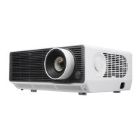
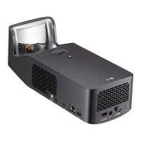
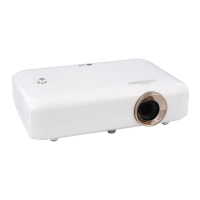
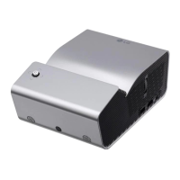
Detailed specifications of the DLP projector, including display type, brightness, and resolution.
Visual representation of the projector's internal components and their interconnections.
Diagram illustrating the optical path and key components of the projector's optical system.
Lists the necessary computer, cables, and software for firmware upgrades.
Step-by-step instructions for updating the projector's firmware using the provided software.
Essential preparatory steps before starting any disassembly procedures, including safety.
Instructions for safely removing the projector's lamp module.
Steps for removing the Input/Output cover assembly.
Procedure for removing the projector's top cover.
Instructions for removing the front cooling fan assembly.
Steps for removing the main circuit board.
Procedure for removing the middle internal cover.
Instructions for removing the ballast module.
Steps for removing the projector's optical engine assembly.
Procedure for removing the power outlet socket.
Instructions for removing the power board assembly.
Steps for removing the rear foot assembly.
Instructions for removing the front foot assembly.
Diagram showing the projector's components in an exploded view for identification.
Diagnosing and resolving issues related to video input signals and display.
Resolving problems with the projector's operational functions, including remote and button failures.
Diagnosing and fixing issues related to the projector's power supply and startup.
Procedures for testing and aligning projector functions after repair or maintenance.
Information on various display modes and patterns used for testing projector performance.
List of compatible video signal resolutions, frequencies, and sizes for testing.
Details specific BMP files and procedures for visual testing of projector output.
Explains the purpose of the connector information section for board diagnostics.
Overview of connectors on the main board, including their general function.
Overview of connectors on the power board, including their general function.
Overview of connectors on the ballast board, including their general function.
Detailed pin assignments and locations for main board connectors.
Pinout and description for the IR receiver connectors.
Pinout and description for the fan control connectors.
Pinout and description for the ballast control connector.
Detailed pin assignments for the keypad control connector.
Pinout and description for the thermal sensor connector.
Pinout and description for video and S-video input connectors.
Pinout and description for the video output connector.
Pinout and description for the S-video output connector.
Pinout and description for the D-SUB analog RGB input connector.
Pinout and description for the stereo audio output connector.
Pinout and description for the color wheel motor connector.
Pinout and description for the main power input connector.
Pinout and description for the USB data connector.
Pinout and description for the CW index connector.
Pinout and description for the firmware debugging interface.
Overview and pinouts for connectors on the power board.
Details for +380V output and DC output connectors on the power board.
Overview and pinouts for connectors on the ballast board.
Pinout and description for the lamp signal connector.
Pinout and description for the 380V DC connector on the ballast board.
Explains the Replacement Parts List (RPL) and ordering procedures for FRU parts.
Lists part numbers and names for components 1 through 10.
Lists part numbers and names for components 11 through 20.
Lists part numbers and names for components 21 through 30.
Lists part numbers and names for components 31 through 33.
Explains the meaning of different LED colors and blinking patterns for status indication.