7
MAJOR COMPONENTS
The following is a general description of each
component and its functions. Please review this
section carefully, as it will give you a better
understanding as to how Nfinity operates.
Unit Frame
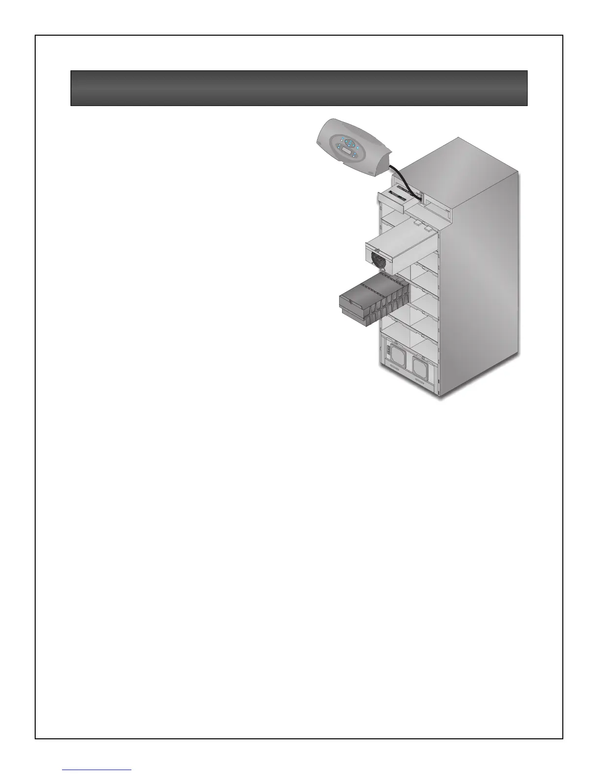
Nfinity’s frame houses all of the other system
components. Looking at the front of Nfinity,onewill
see a series of plastic bezels. By grasping these
bezels from the side and pulling out, you will
remove the bezel to reveal the Battery / Power
Module bays. The bottom bezel covers the cooling
fans and the Manual Bypass Switch.
The User Interface Module is located above the
Power / Battery Module bays for easy access.
From here the user may find out various
information about Nfinity’s condition. By moving
the User Interface and setting it on top of the
frame, you will see the System Control Module
bays.
Nfinity’s frame with bezels removed
(Power Module and Battery Module extended for illustration
only. Extending more than one module at a time could cause
the unit to tip over).
ESC
!