8
User Interface Module
The User Interface Module is the primary source of
communication between the UPS and the user.
From the interface, the user can:
• View the status of the UPS
• Custom configure the system
• Review the event log to assist with
troubleshooting
• Enable / disable the output power
• Silence the audible alarm
For a more detailed explanation on how to operate
the User Interface module, see Controls And
Indicators on page 19.
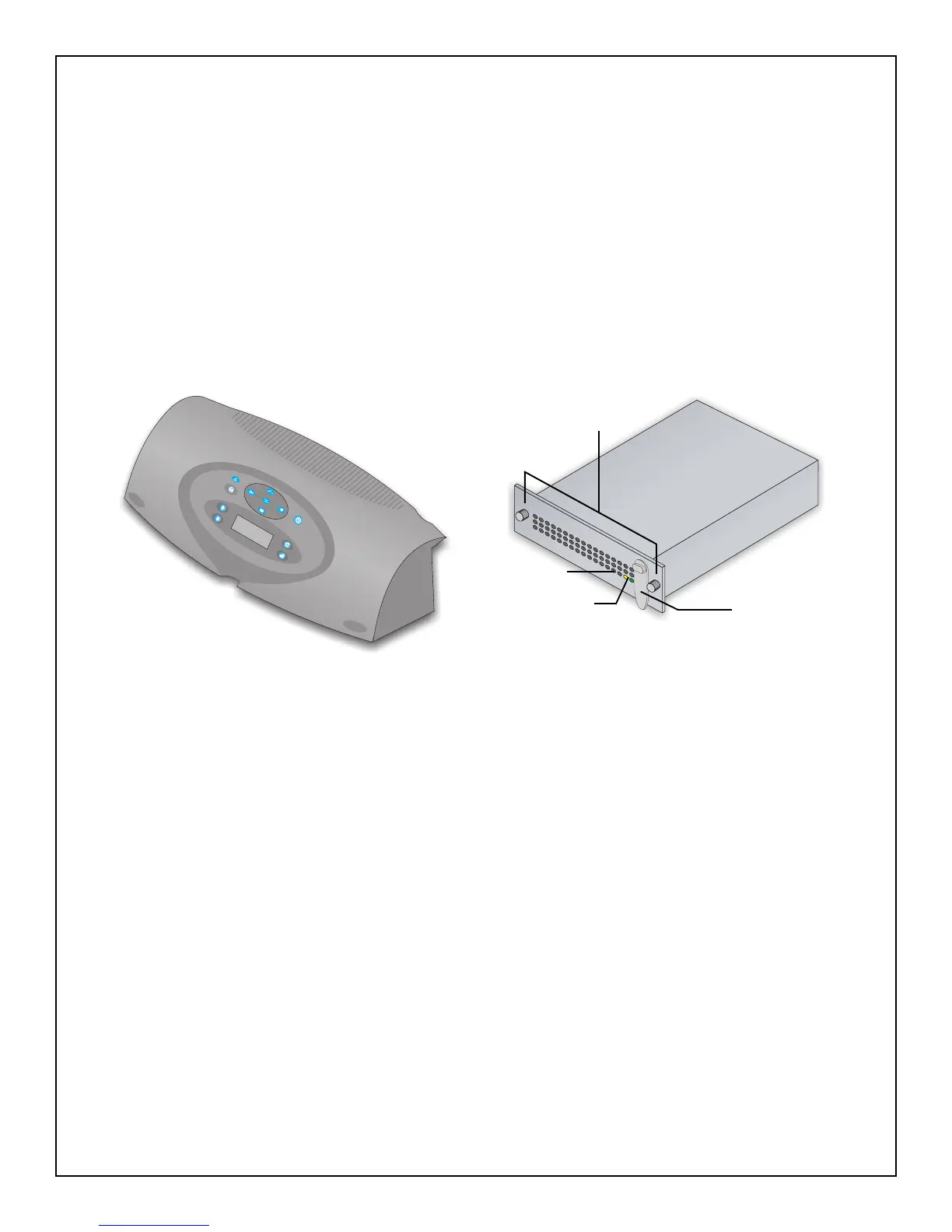
User Interface Module
System Control Module
The System Control Module is the communicative
backbone of the UPS. It gathers input from all
modules and processes the data to control the
operation of the system — including monitoring the
condition of each module. An optional second
System Control Module can be installed to provide
full system redundancy (operation and
communication), in the unlikely event a Control
Module should fail.
Under normal operation, the Status LED (green)
will blink and the Fault LED (amber) will be off. For
any condition other than this, check
Troubleshooting on page 34.
System Control Module
Lever
Fault LED
Status LED
Fasteners