Electrical Connections
16
2.3.3 BCB Box Interface
J10 is the BCB box interface.
2.3.4 Output Dry Contacts
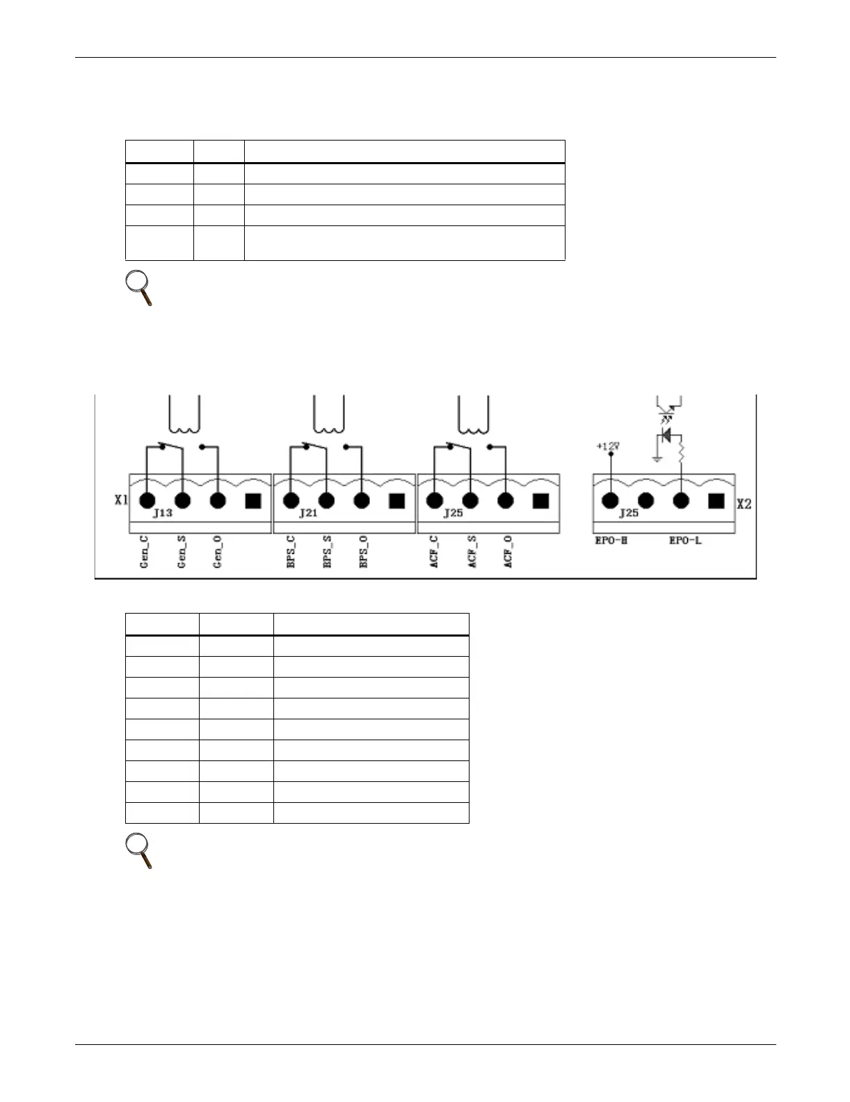
There are three output dry contact relays at the X1 slot (see Figure 9 and Table 4).
Figure 9 Output dry contacts and EPO wiring
Table 3 BCB box interface
Position Name Description
J10.1 DRV BCB Driver Signal - Output (N.O.)
J10.2 FB BCB Contact State - Input (N.O.)
J10.3 GND Power Ground
J10.4 OL
BCB On-Line - Input - This pin will become active when
BCB interface is connected. (N.O.)
NOTE
All auxiliary cables of terminal must be double insulated. Wire should be 16-20AWG stranded.
Table 4 Output dry contact relays
Position Name
Description
J13.2 Gen_O Generator Start Relay (N.O.)
J13.3 Gen_S Generator Start Relay Center
J13.4 Gen_C Generator Start Relay (N.C.)
J21.2 BPS_O Bypass Mode Relay (N.O.)
J21.3 BPS_S Bypass Mode Relay Center
J21.4 BPS_C Bypass Mode Relay (N.C.)
J25.2 ACF_O Main Input Fault Relay (N.O.)
J25.3 ACF_S Main Input Fault Relay Center
J25.4 ACF_C Main Input Fault Relay (N.C.)
NOTE
All auxiliary cables of terminal must be double insulated. Wire should be 16-20AWG stranded.