Installation Drawings
46
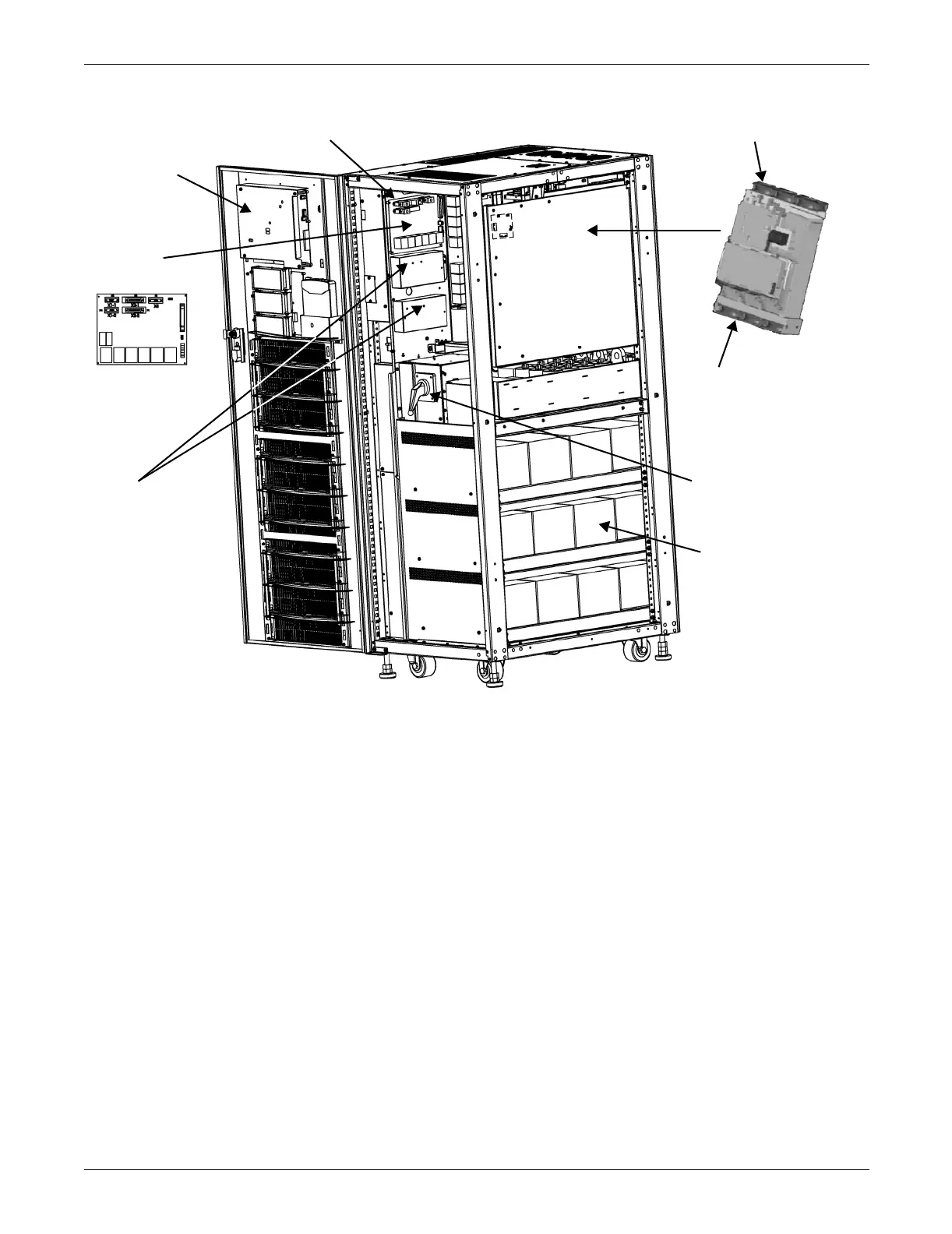
Figure 25 Main components—typical unit
Fans
Fans
POWER
MODULE
NOTES
1. Main components are shown in the drawing.
2. Typical options are shown; actual positions on control wiring may vary depending on which options
are included on your unit.
3. Refer to 3.0 - Battery Installation for battery installation details.
4. All wiring must be installed in accordance with all national and local electrical codes.
Monitor
Board - U2
Parallel
Logic
Board - M3
Battery Start (optional)
in left side
Surge
Protection
(optional)
Rotary Switch
Batteries