Battery Installation
25
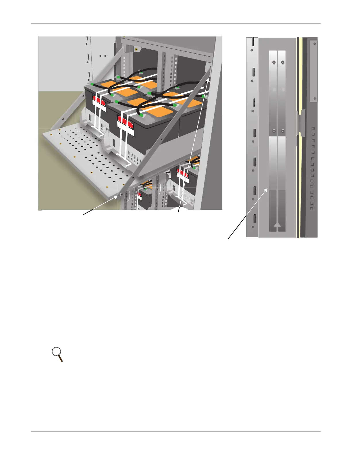
Figure 13 Battery tray and supports
3.7.2 Connecting the Battery Cabinet to the UPS
After the battery cabinet equipment has been positioned and secured for operation and the batteries
have been connected, connect the power cables as described below. (See Figure 30.)
1. Verify that all incoming high and low voltage power circuits are de-energized and locked out or
tagged out before installing cables or making any electrical connections.
2. Remove the UPS left side panel to gain access to the connection bars.
3. Remove the battery cabinet front panel to gain access to the connection bars.
4. Connect the safety ground and any necessary bonding ground cables to the copper ground busbar.
(example: UPS located on the bottom of the equipment below the power connections).
All cabinets in the UPS system must be connected to the user's ground connection.
5. Connect the system battery cables from the UPS battery output terminals (+ N -) to battery
cabinet BCB (+ N -) as shown in Figure 30. Be sure that the battery connector is made with the
right polarity, and tighten the connections to 44 lb-in. (5 N-m) (M6 Bolt). Do not close the battery
circuit breaker before the equipment has been commissioned.
6. Connect supplied auxiliary control cable to pins J10.2 and J10.3 on the U2 monitoring board (see
2.3 - Dry Contacts). Add a jumper wire between J10.3 and J10.4.
NOTE
The grounding and neutral bonding arrangement must be in accordance with the National
Electrical Code and all applicable local codes.
Slot in support secured by screw-in
connector at corner of battery tray ...
... and notched end of support
slips into slot at top corner
of battery compartment
Battery tray supports attach to interior
surface of NX front door

 Loading...


