Maintenance Bypass Cabinet
29
4.6.2 Power Cable Installation
Refer to Table 22 when selecting cables.
4.6.3 Input/Output Wiring
Follow the steps below to connect the input wiring:
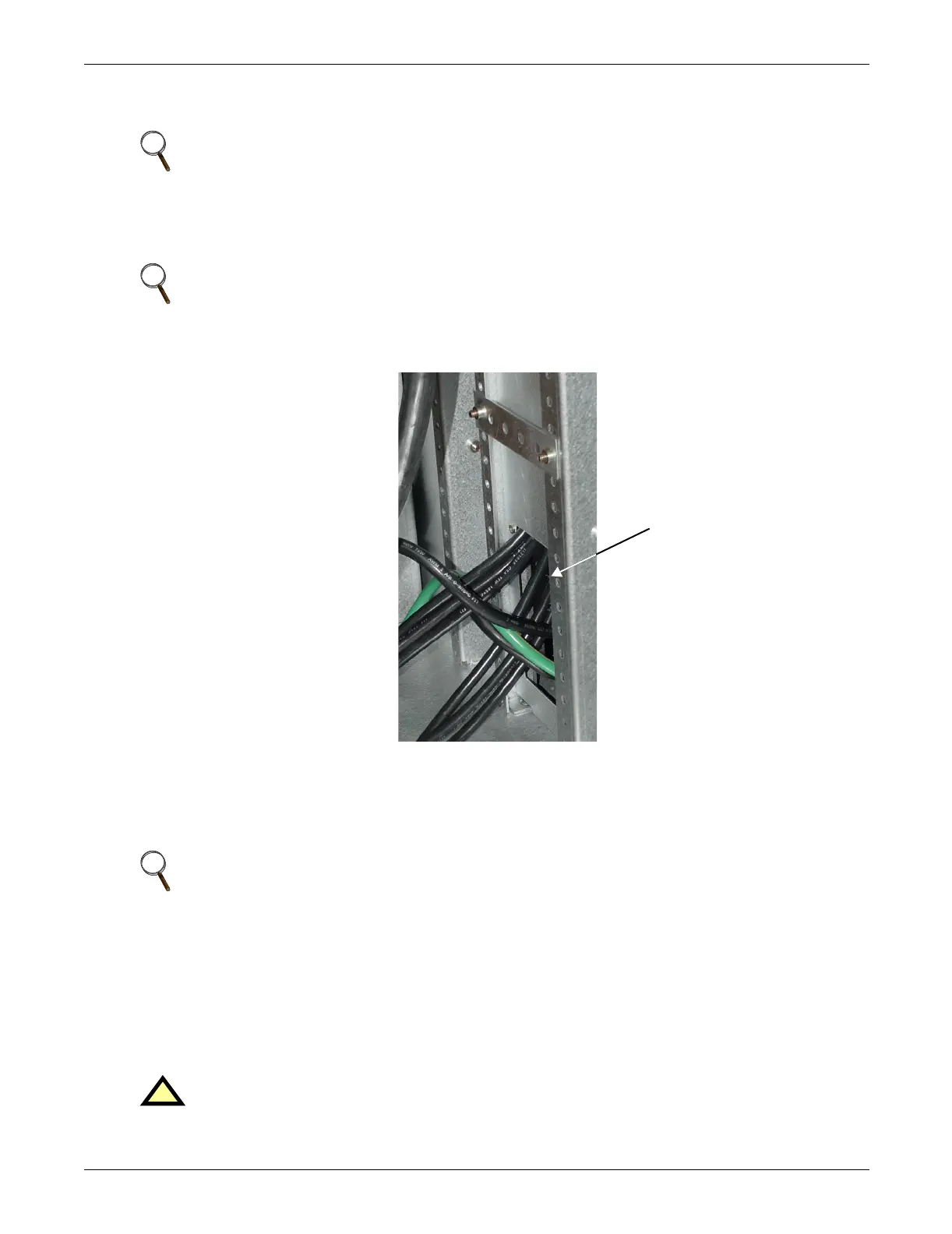
1. Locate the input wiring access (top or bottom access), remove the knockout and pull the three/four
input wires through it, allowing some slack for installation. See Figure 16.
Figure 16 Maintenance Bypass Cabinet wiring access panel
2. Secure the conduit to the access plate of the Maintenance Bypass Cabinet.
3. Input power cables connect to the system input circuit breaker. Refer to Figure 31 -
Maintenance Bypass interconnection
4. Connect the ground (earth) wire to the earth busbar and tighten it to 44 lb-in. (5 N-m) (M6 bolt).
5. Locate UPS input and output cables and access panel to UPS on lower right side.
6. Connect the system ground cable between the Maintenance Bypass Cabinet and UPS and tighten
the connections to 44 lb-in. (5 N-m) (M6 bolt).
7. Connect the system input cables between the Maintenance Bypass Cabinet 'UPS Input' Busbars
(A-B-C N terminals) and UPS input busbars (A-B-C N terminals) and tighten the connections to
44 lb-in. (5 N-m) (M6 bolt).
8. Connect the system input cables between the Maintenance Bypass Cabinet 'UPS Output' Busbars
(A-B-C N terminals) and UPS output busbars (A-B-C N terminals) and tighten the connections to
44 lb-in. (5 N-m) (M6 bolt).
9. Connect supplied dry contact wire to X3 on the Parallel (M3) board (see Figure 17).
NOTE
Transient and steady state earth leakage currents may occur when starting the equipment.
This should be taken into account when selecting ground current detection devices because
these will carry the earth leakage currents of both the UPS equipment and the load.
NOTE
Input wiring must be installed using conduit.
NOTE
Cabinet is not to be bolted to the UPS, use either top or bottom access plate.
!
WARNING
The dry contact wire must be installed to ensure proper operation of the system and fully
protect the load when switching between bypass cabinet and UPS.
Wiring access is on
lower right side of
Maintenance
Bypass Cabinet
Access panel removed,
wiring connects NX and MBC