User Manual 10H52192UM60 - Rev. 1 - 09/2011 13
Installing the UPS Module Liebert NX
1.7 Power Cable
The cable design must comply with the instructions provided in this section, conform to local wiring practices, take the
environmental conditions into consideration, and comply with IEC60950-1.
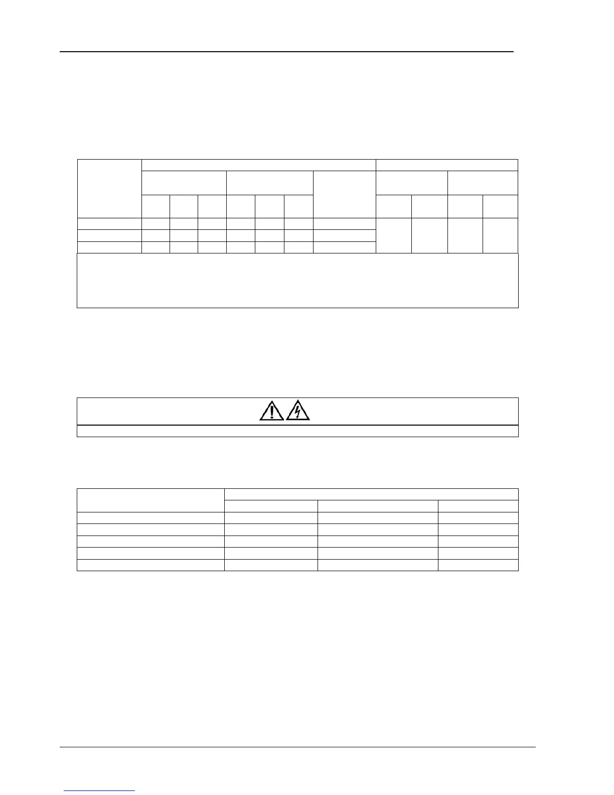
1.7.1 Maximum Steady State AC and DC Currents
Table 1-1 Maximum Steady State AC and DC Currents
UPS rating (kVA)
Rated current (A) Busbar stud size
Input mains current
1
,
2
with full battery recharge
Output current
2
at full
load
Battery discharge
current at EOD
3
(32 blocks)
Main input, output,
bypass input cables
Battery cables
380V 400V 415V 380V 400V 415V Bolt
Torq ue
(Nm)
Bolt
Torq ue
(Nm)
60 112 106 102 90 86 82 200
M8 15 M8 15
40 75 71 68 60 57 55 133
30 56 53 51 45 43 41 100
Note:
1. Input mains current for common rectifier and bypass AC input.
2. Non-linear loads (switch mode power supplies) affect the design of the output and bypass neutral cables. The current
circulating in the neutral cable may exceed the nominal phase current. A typical value is 1.7 times of the rated current.
3. The battery discharge current should change with the battery voltage.
1. Protective earth cable: Follow the most direct route possible when connecting the earth cable to the cabinet. The size of the
earth cable is to be determined according to the AC supply fault rating, cable lengths, and type of protection.
2. When sizing the battery cables, a maximum volt drop of 4 Vdc is permissible at the current ratings given in Table 1-1. The load
equipment is generally connected to a distribution board containing individually protected busbars rather than being connected
directly to the UPS output. The output cables from units in parallel to the parallel distribution bus should be the same type in order
to optimize current sharing. To minimize the electromagnetic interference, avoid forming coils.
3. See Figure 1-4 for the position of the terminals.
Warning
Failure to follow adequate earthing procedures may result in electromagnetic interference or in hazards such as electric shock or fire.
1.7.2 Distance from Floor to Connection Point on the Equipment
Table 1-2 Distance from Floor to Connection Point on the Equipment
UPS connection point
Minimum distance (mm)
30 kVA 40 kVA 60 kVA
Rectifier AC input supply 1000 1000 1000
Bypass AC input supply 1000 1000 1000
UPS AC output 1000 1000 1000
Battery power 1000 1000 1000
Auxiliary cable to monitoring board (U2) 1104 1104 1104