18 User Manual 10H52192UM60 - Rev. 1 - 09/2011
Liebert NX Installing the UPS Module
1.8.2 BCB Port
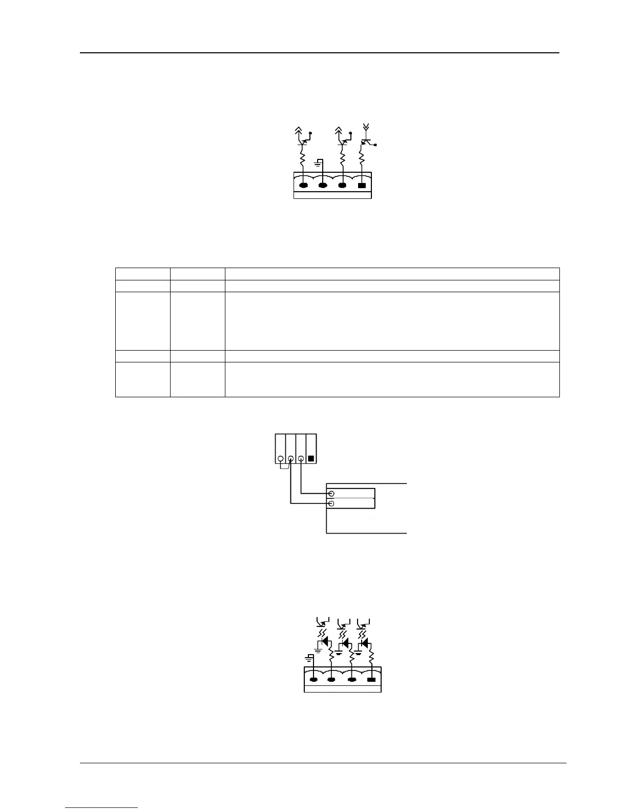
J6 is the BCB port. The port is shown in Figure 1-7 and described in Table 1-4.
12V
OL
GND
FB
DRV
J6
12V
12V
Figure 1-7 BCB Port
Table 1-4 BCB Port Description
Position Name Description
J6.1 DRV BCB driver signal (only for use with BCB control board)
J6.2 FB
BCB contact state. Connection J6.2 to J6.3.
If the internal BCB is in the open position, the BCB auxiliary contact is open.
The requirement for the external BCB auxiliary is as follows:
If the external BCB is in the open position, the external BCB auxiliary contact must be open.
This contact is only active if J6.3 and J6.4 are closed.
J6.3 GND Power ground
J6.4 OL
BCB on line
If the “BCB Contact State” is used, J6.3 and J6.4 must be closed.
(The same applies to use with BCB control board)
The connection between the BCB port and BCB is shown in Figure 1-8.
电池开关
BCB
J10
OL
GND
FB
DRV
Aux-N.O.
Aux-N.O.
J6
Aux_N.O.
Aux_N.O.
BCB
Figure 1-8 Connection Between BCB Port and BCB
1.8.3 Maintenance Switch and Output Switch State Port
J9 is the maintenance switch and output switch state port. The port is shown in Figure 1-9 and described in Table 1-5.
EXT-S
CAB-S
CAB-S
J9
EXT_Q3
IN_S
GND
EXT_OUT
Figure 1-9 Maintenance Switch and Output Switch State Port