User Manual 10H52192UM60 - Rev. 1 - 09/2011 47
Operating Instructions Liebert NX
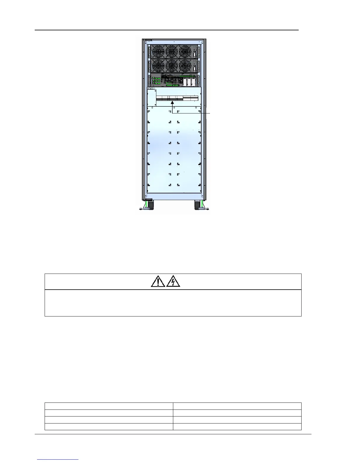
Figure 6-2 Location of Maintenance Switch of 40-60 kVA UPS
6.2 UPS Startup Procedures
These procedures are based on the assumption that the installation is complete, the system has been commissioned by authorized
personnel, and the external protective devices are closed.
6.2.1 Procedure for Startup in Normal Mode
Warning
1. These procedures result in mains voltage being applied to the UPS output terminals.
2. If any load equipment is connected to the UPS output terminals, check with the user that it is safe to apply power. If the load is not
ready to receive power, ensure that it is safely isolated from the UPS output terminals.
3. Do not start the UPS until the installation procedures are complete and the system has been commissioned by authorized personnel.
Use the following procedure to turn on the UPS from a fully powered down condition. In a parallel system, perform each step of the
procedure on every UPS module before proceeding to the next step.
1. Close the UPS input switches QS1 (mains input) and QS2 (bypass input) to connect the mains power to the UPS.
At this point, the LCD starts up. The rectifier indicator flashes green during rectifier startup. About 30 seconds after the rectifier
enters normal operation, the green rectifier indicator remains on (not flashing). After system initialization, the bypass STS is closed
and the green bypass indicator remains on (not flashing). The red battery indicator is illuminated.
2. Close the internal and/or external battery circuit breakers (internal QS6 and QS7).
At this point the battery indicator turns off.
3. Close the output switch QS4.
The UPS indicator states are as listed in Table 6-1.
Table 6-1 UPS Indicator State
Indicator State
Rectifier indicator Green
Battery indicator Off
Bypass indicator Green
Maintenance switch