User Manual 10H52192UM60 - Rev. 1 - 09/2011 19
Installing the UPS Module Liebert NX
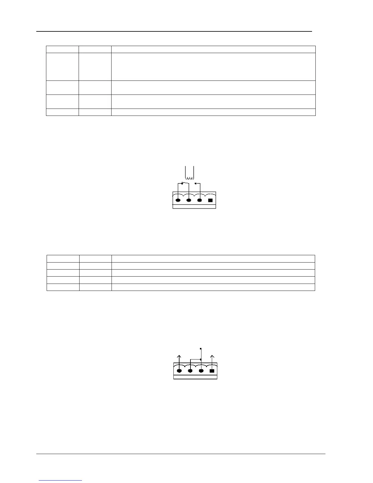
Table 1-5 Description of Maintenance Switch and Output Switch State Port
Position Name Description
J9.1 EXT_Q3
External maintenance switch state. Connection J9.1 to J9.4.
The requirement for the external breaker auxiliary is as follows:
If the external maintenance switch is in the open position, the external bypass auxiliary contact must
be closed. If this function is not in use, J9.1 and J9.4 must be closed.
J9.2 IN_S
Internal maintenance switch state. Connection J9.2 to J9.4.
If the internal maintenance switch is in the open position, the bypass auxiliary contact is open.
J9.3 EXT_OUT
Internal output switch state. Connection J9.3 to J9.4.
If the internal output switch is in the open position, the output auxiliary contact is open.
J9.4 GND Power ground
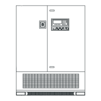
1.8.4 Output Dry Contact Port (Backfeed Protection)
J5 is the output dry contact port. It provides two relay output dry contact signals. The port is shown in Figure 1-10 and described in
Table 1-6. The shunt trip coil of the external air breaker can be driven directly via this dry contact. The shunt trip coil of the external
air breaker should be 250 Vac / 5 A or 24 Vdc / 5A.
J5
BFP_C
BFP_S
BFP_O
Figure 1-10 Output Dry Contact Port
Table 1-6 Description of Output Dry Contact Port
Position Name Description
J5.1 - Free
J5.2 BFP_O Bypass backfeed protection relay (normally open), closed to J5.3 if bypass SCR is shorted
J5.3 BFP_S Bypass backfeed protection relay center
J5.4 BFP_C Bypass backfeed protection relay (normally closed), open to J5.3 if bypass SCR is shorted
1.8.5 Remote EPO Input Port
The UPS has an EPO function that operates by a button on the operator control and display panel of the UPS or by a remote contact
provided by the user. The EPO switch is under a hinged, plastic shield.
J10 is the remote EPO input port. The port is shown in Figure 1-11 and described in Table 1-7.
J10
+12V
EPO_NO
+12V
+12V
EPO_NC
Figure 1-11 Remote EPO Input Port