28 User Manual 10H52192UM60 - Rev. 1 - 09/2011
Liebert NX Installing Parallel Systems
Chapter 3 Installing Parallel Systems
This chapter describes how to install and connect a parallel system.
3.1 Overview
Up to four UPS units can be connected in parallel to form a parallel system. Parallel systems must be installed in accordance with
the UPS module installation procedures and the requirements outlined in this chapter.
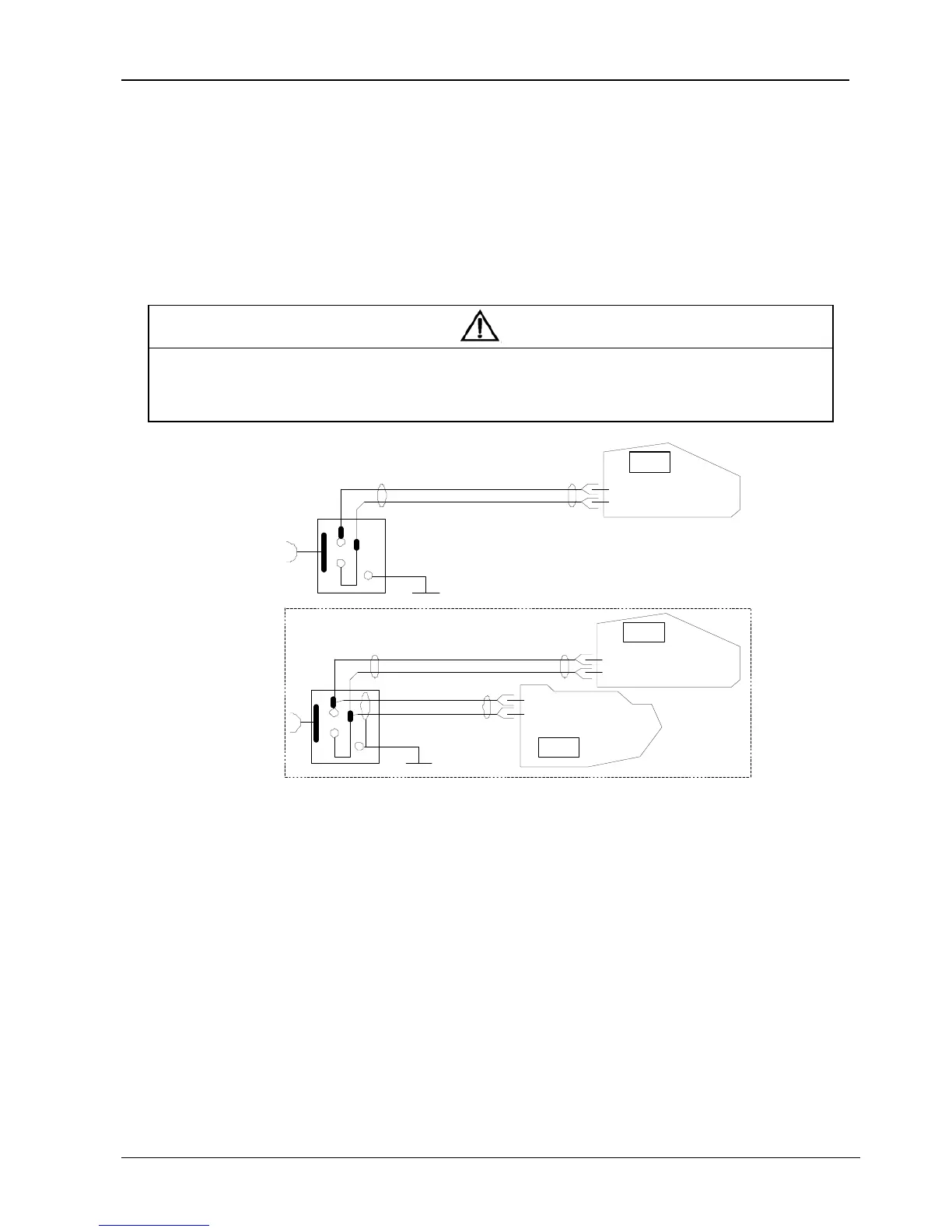
In addition to the EPO switch provided on the operator control and display panel of each UPS module for controlling the EPO of
each module respectively, the parallel system also provides a remote EPO function so that all the UPS modules can be shut down
simultaneously from a remote terminal, as shown in Figure 3-1.
Note
1. The remote EPO switch must provide a dry contact signal, which is normally open or closed.
2. The open circuit voltage provided is 5 Vdc, < 20 mA.
3. The external EPO device may consist of another control system that can disconnect the UPS mains supply or the bypass input.
4. A jumper is connected between pins 1 and 2 of the normally closed EPO-J10 port on the bypass module in the factory.
UPS 1
J10: 3
J10: 4
J10: 3
J10: 4
UPS 2
UPS 1
Bypass module
Bypass module
J10: 3
J10: 4
Bypass module
Figure 3-1 EPO Circuit Diagram
3.2 1 + N Parallel System
The basic installation steps for a parallel system are the same as for the UPS module. The following sections describe the differences
between the procedure for installing the parallel system and the procedure for installing the UPS module.
3.2.1 Installing the Cabinet
Position the UPS modules and connect them as shown in Figure 3-2. The output distribution, consisting of the external UPS output
switches and maintenance bypass, must be installed as shown in Figure 3-2, in order to facilitate maintenance and system testing.