30 User Manual 10H52192UM60 - Rev. 1 - 09/2011
Liebert NX Installing Parallel Systems
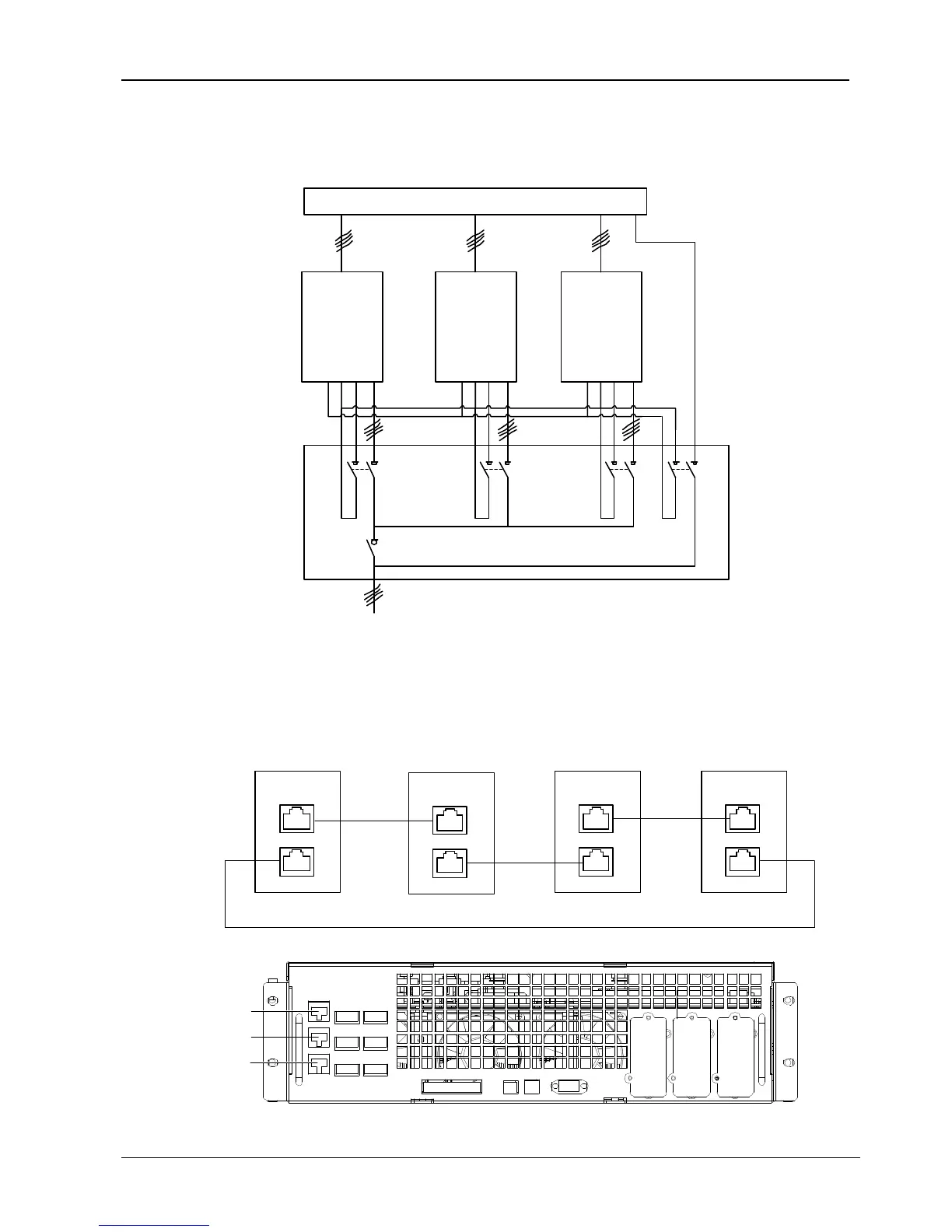
3.2.4 Auxiliary Control Wiring
Auxiliary wiring must be installed as shown in Figure 3-3 to protect the system and enable a single UPS to be isolated and tested
during service. Refer to 1.8.3 Maintenance Switch and Output Switch State Port for auxiliary contact details.
Input dist ribution
UPS 3
J9
143
UPS 2
J9
143
UPS 1
J9
143
Q1Ext
Q2Ext
QByp
QUPS
Q2Ext
Dist ribution panel
To load
Figure 3-3 Auxiliary Control Wiring
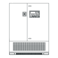
3.2.5 Parallel Control Cables
Shielded and double-insulated parallel control cables available in lengths of 5 m, 10 m and 15 m must be interconnected in a ring
configuration between the UPS modules, as shown in Figure 3-4. The parallel ports J2 and J3 are provided on the front panel of the
bypass module, as shown in Figure 3-5. The ring connection ensures the reliability of the control of the parallel system. Be sure that
the cables are connected correctly before starting up the system!
J2
J3
UPS 1
J2
J3
UPS 2
J2
J3
UPS 3
J2
J3
UPS 4
Figure 3-4 Connection of Parallel Control Cables of 1+N Parallel System
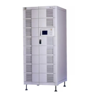
J2
J3
J4
Figure 3-5 Locations of Ports J2, J3 and J4 on Bypass Module