User Manual 10H52192UM60 - Rev. 1 - 09/2011 31
Installing Parallel Systems Liebert NX
3.3 Dual Bus System
3.3.1 Installing the Cabinet
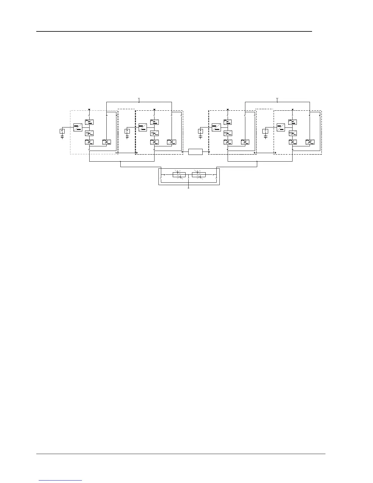
A dual bus system consists of two independent UPS systems, each containing one or more parallel UPS modules (maximum 4), as
shown in Figure 3-6. The dual bus system has high reliability and is suitable for loads with multiple input terminals. For single-input
loads, an optional STS can be fitted to start the LBS supplied in standard configuration.
UPS 1
Bypass
UPS 1
LBS
To load
Main input
UPS4 UPS4
Main input Main inputMain input
Parallel
control
cable
Parallel
control
cable
Bypass
STS
Figure 3-6 Typical Dual Bus System (with STS and LBS)
The dual bus system uses the LBS to keep the output of the two independent UPS systems (or parallel systems) in synchronization.
One system is designated as the master; the other is designated as the slave. The operating modes of the parallel system comprise
master and/or slave operation in normal or bypass mode.
Place the UPS modules side by side and connect the UPS modules together as described below.
3.3.2 External Protective Device
Refer to Chapter 1 Installing the UPS Module.
3.3.3 Power Cable
The wiring of power cables is similar to that of single module system. The bypass and the main input sources must be referenced to
the same neutral potential, and input earth leakage monitoring devices, if installed, must be located upstream of the common
neutral sinking point. Refer to Chapter 1 Installing the UPS Module.
3.3.4 Control Cable
For NX-to-NX dual bus systems, connect the optional LBS cables between the two UPS systems as shown in Figure 3-7 to Figure 3-9.
The J3 and J4 ports are provided on the front panel of the bypass module, as shown in Figure 3-5.