User Manual 10H52192UM60 - Rev. 1 - 09/2011 15
Installing the UPS Module Liebert NX
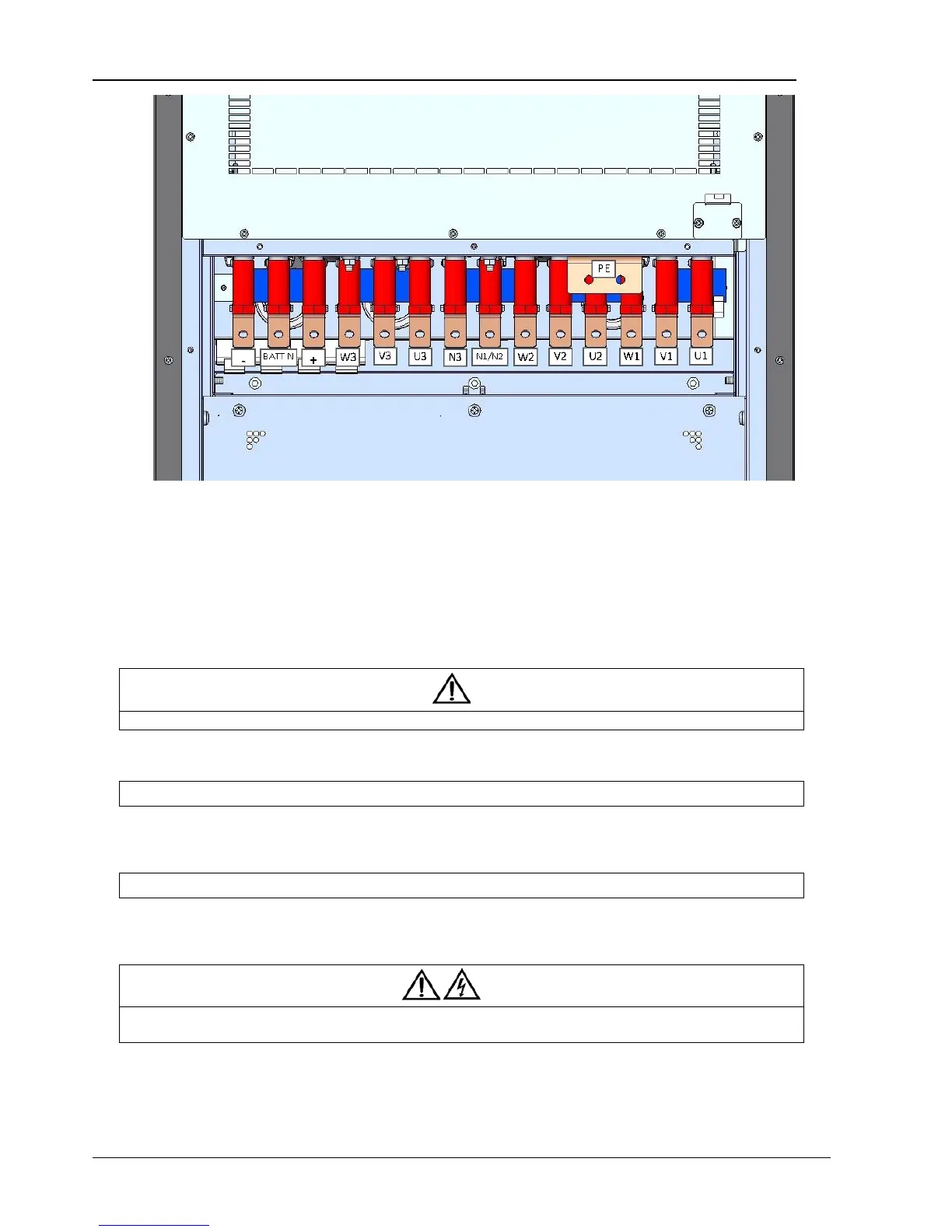
Figure 1-4 UPS Power Terminals
Note:
1. Main input: U1, V1, W1, N1
2. Bypass input: U2, V2, W2, N2
3. UPS output: U3, V3, W3, N3
4. Battery input: +, -, BATT N
5. Earth: PE
3. Connect the protective earth cable and all other earth cables required to the earth terminals (PE).
Note
The earth cables and neutral line connection must comply with local and national codes of practice.
4. Identify and connect power connections for the input cables according to one of the following two procedures, depending on
the type of installation.
Common Input Connections
1) For a common bypass and rectifier input configurations for 30kVA to 60kVA UPS, connect the AC input cables to the rectifier
input terminals (U1-V1-W1-PEN1) and to the bypass input terminals (U2-V2-W2-PEN2). See Table 1-1 for the torque. Ensure correct
phase rotation.
Separate Bypass Connections
2) For separate bypass configurations, connect the main input cables to the rectifier input terminals (U1-V1-W1-PEN1), and
connect the bypass input cables to the bypass input terminals (U2-V2-W2-PEN2). See Table 1-1 for the torque. Ensure correct phase
rotation.
Warning
For separate bypass operation, ensure that the linking busbars between the bypass input and main input are removed. The rectifier
input and bypass input must be referenced to the same neutral point.