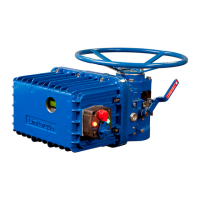
WTR Series
Contents / Figures / Tables
L120 Installation & Maintenance Manual 120-11000 A
Reassembly 24
Declutch Assembly (L120-10) 25
Declutch Assembly (L120-20/40) 26
Install the Motor 26
How to Order Parts 26
Figures
Figure 1 – L120-10 through 40 2
Figure 2 – Micro-Switch Style Torque Switch and 600 Volt Torque Switch 6
Figure 3 – Limit Switch 7
Figure 4 - Setting the open and closed contacts 8
Figure 5 – 1000 ohm Potentiometer 10
Figure 6 – L120-10 dimensions and parts 11
Figure 7 – L120-20 dimensions and parts 12
Figure 8 – L120-40 dimensions and parts 13
Figure 9 – L120-10 through 40 typical wiring diagram 15, 16
Figure 10 – L120-10 through 40 unit, drive sleeve and housing parts breakdown 17, 18
Figure 11 – L120-10 through 40 standard and extended drive sleeve assembly 22
Figure 12 – L120-10 through 40 thrust base 23
Figure 13 – L120-10 through 40 declutch assembly parts beakdown 25
Tables
Table 1 – Unit weights 3
Table 2 – Mounting Base Dimensions 4
Table 3 – Stem Acceptance 5
Table 4 – Lubricant Weights 20
VI

 Loading...