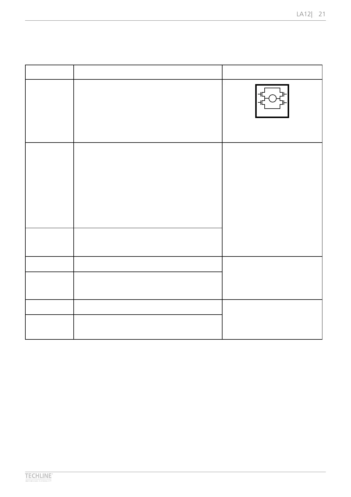
Actuator with IC and Endstop Signals
I/O specifications
Input/Output Specification Comments
Description Easy-to-use interface with integrated power
electronics (H-bridge)�
The actuator can also be equipped with an
electronic circuit that gives an absolute or relative
feedback signal�
The version with “IC option” cannot be operated
with PWM (power supply)�
M
H-Bridge
Brown 12-24 V DC
Connect Brown to positive (VDC)
12 V ± 20 %
24 V ± 10 %
Under normal conditions:
12 V, max� 5 A (depending on load)
24 V, max� 2�5 A (depending on load)
Note: Do not change the power
supply polarity on the Brown and
Blue wires!
If the temperature drops below
0 °C, all current limits will
automatically increase to 11 A�
Blue 12-24 V DC
Connect Blue to negative (GND)
Red Extends the actuator On/off voltages:
> 67 % of V
IN
= ON
< 33 % of V
IN
= OFF
Input current: 10 mA
Black Retracts the actuator
Green Endstop signal out Output voltage min� V
IN
- 1 V
Source current max� 100 mA
Endstop signals are NOT potential
free�
Yellow Endstop signal in
 Loading...