Actuator with Reed - Relative positioning 3 wires
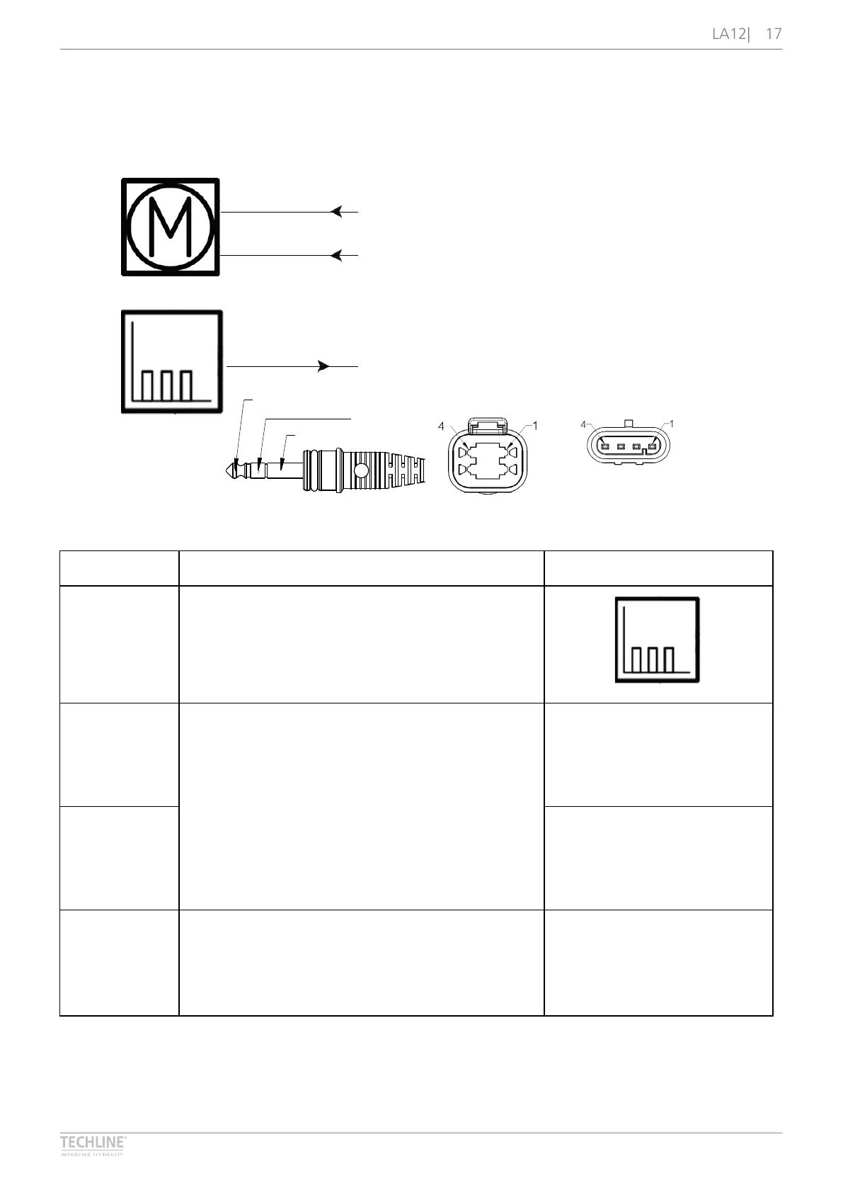
Connection diagram
Fig� 8: 12xRxx-xxxxxxx2/3
8
2019 © LINAK A/S
Reed - Relative positioning 3 wires
12XRXX-XXXXXXX2/3
BROWN
BLACK
BLUE
REED OUTPUT
Please be aware that if the power supply is not properly connected, you might damage the actuator!
2 2
1 1
3 3
DEUTSCH AMP
Brown
Black
Blue
I/O specifications
Input/Output Specification Comments
Description The actuator can be equipped with a Reed sensor
and a spindle magnet that give a relative positioning
feedback signal when the actuator moves� The
output signal is a PNP signal�
See Connection Diagram�
Brown 12 or 24 V DC (+/-)
12 V ± 20 %
24 V ± 10 %
Under normal conditions:
12 V, max� 5 A (depending on load)
24 V, max� 2�5 A (depending on load)
To extend actuator:
Connect Brown to positive
To retract actuator:
Connect Brown to negative
Black To extend actuator:
Connect Blue to negative
To retract actuator:
Connect Blue to positive
Blue Reed output: same as input voltage - 1 V
4 pole magnet (Option R)
2 mm pitch = 0�5 mm per
count
4 mm pitch = 1�0 mm per
count
6 mm pitch = 1�5 mm per
count
Max� switching capacity: 750
mA