Connection diagram
Fig� 4: 12xxxx-xxxxxxx0/1
4
2019 © LINAK A/S
Without feedback
BROWN
BLUE
12X0XX-XXXXXXX0/1
Please be aware that if the power supply is not properly connected, you might damage the actuator!
2 2
1 1
DEUTSCH AMP
Brown
Blue
I/O specifications
5
2021 © LINAK A/S
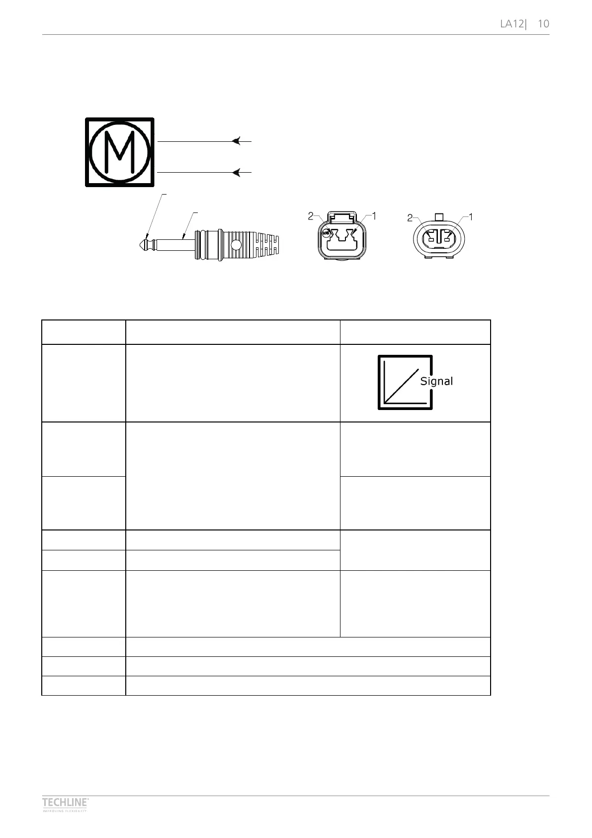
Absolute positioning - Mechanical potentiometer feedback
Input/Output Specification Comments
Description The actuator can be equipped with a mechanical potentiometer
that gives an analogue feedback signal when the actuator moves
RED 12 or 24 VDC (+/-)
12 V ± 20 %
24 V ± 10 %
Under normal conditions:
12 V, max. 5 A depending on load
24 V, max. 2.5 A depending on load
To extend actuator:
Connect Red to positive
To retract actuator:
Connect Red to negative
Blue To extend actuator:
Connect Blue to negative
To retract actuator:
Connect Blue to positive
Green Signal power supply (+) 12-24 VDC +10 V or other value
Black Signal power supply GND (-)
Yellow Potentiometer feedback
Slide potentiometer, 10 kohm
1 kohm = 0 mm stroke
11 kohm = 100 mm stroke
The maximum effect: 0.1 W
Linearity: ± 20 %
Minimum lifetime: 15,000 cycles
Average lifetime: 40,000 cycles
Max. current output: 1 mA
Violet Not to be connected
White Not to be connected
Brown Not to be connected