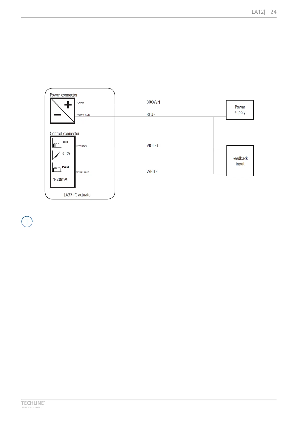
Correct wiring of Power GND and Signal GND for IC
Please note that this section only applies for the following feedback options: 0-10 V, Hall and PWM�
When using the feedback output, it is important to use the right connection setup� Attention should be
paid to the two ground connections: Power GND in the Power Connector and Signal GND in the Control
Connector� When using either Analogue feedback or Mechanical potentiometer feedback, the Signal
GND must be used� For optimal accuracy, the Signal GND is connected to the Power GND
as close to the
feedback input equipment as possible�
Figure 11