Actuator with absolute positioning - Analogue feedback
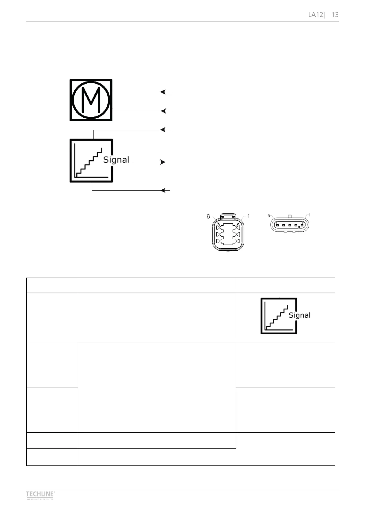
Connection diagram
Fig� 6: 12xxxx-xxxxxxx0
6
2019 © LINAK A/S
Absolute positioning - Analogue feedback
12XB/CXX-XXXXXXX0
YELLOW
BLACK
GREEN
+
-
RED
BLUE
Please be aware that if the power supply is not properly connected, you might damage the actuator!
2 2
1 1
5
3
4
5
3
4
DEUTSCH AMP
I/O specifications
Input/Output Specification Comments
Description The actuator can be equipped with an electronic
circuit that gives an analogue feedback signal when
the actuator moves�
See Connection Diagram�
Red 12 or 24 V DC (+/-)
12 V ± 20 %
24 V ± 10 %
Under normal conditions:
12 V, max� 5 A (depending on load)
24 V, max� 2�5 A (depending on load)
To extend actuator:
Connect Brown to positive
To retract actuator:
Connect Brown to negative
Blue To extend actuator:
Connect Blue to negative
To retract actuator:
Connect Blue to positive
Green Signal power supply (+) 12-24 V DC Current consumption:
Max� 60 mA, also when the
actuator is not running
Black Signal power supply GND (-)