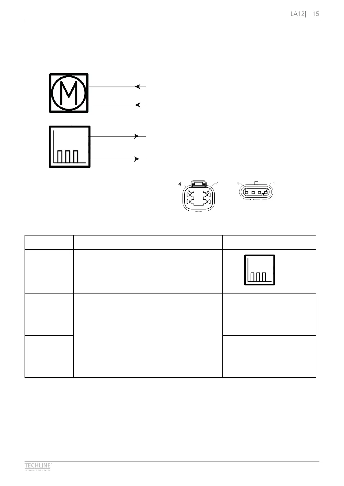
Actuator with Reed - Relative positioning 4 wires
Connection diagram
Fig� 7: 12xxxx-xxxxxxx4
7
2019 © LINAK A/S
Reed - Relative positioning 4 wires
12XXXX-XXXXXXX4
RED
BLUE
WHITE
BLACK
REED OUTPUT
Please be aware that if the power supply is not properly connected, you might damage the actuator!
2 2
1 1
3
4
3
4
DEUTSCH AMP
I/O specifications
Input/Output Specification Comments
Description The actuator can be equipped with a Reed sensor
and a spindle magnet that give a relative positioning
feedback signal when the actuator moves� The
output signal is a PNP signal�
Red 12 or 24 V DC (+/-)
12 V ± 20 %
24 V ± 10 %
Under normal conditions:
12 V, max� 5 A (depending on load)
24 V, max� 2�5 A (depending on load)
To extend actuator:
Connect Red to positive
To retract actuator:
Connect Red to negative
Blue To extend actuator:
Connect Blue to negative
To retract actuator:
Connect Blue to positive