Power and Ground Wiring 19
© 2009 Link
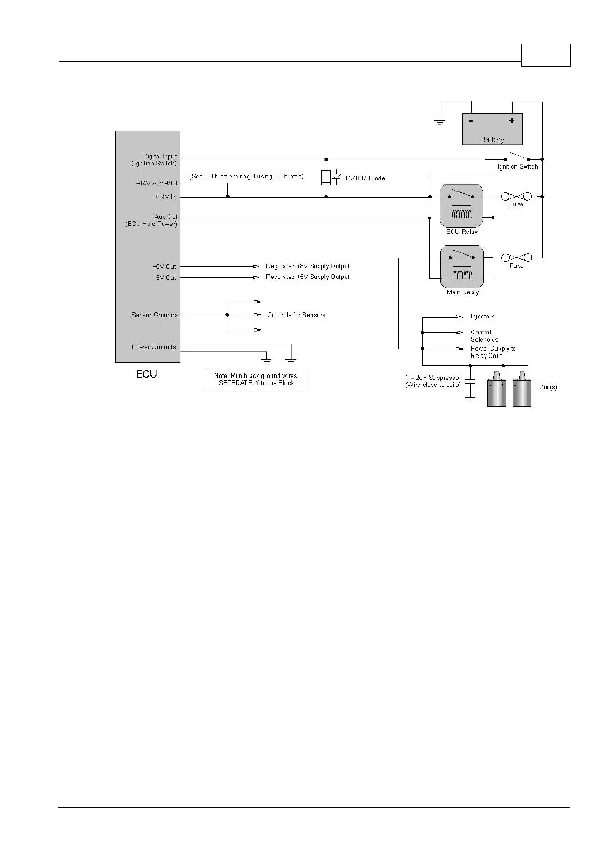
ECU Hold Power Wiring
7 Input Signal Wiring
The following sections describe wiring of the various types of sensors used as inputs to the
G4 ECU.
7.1 Trigger Inputs
Trigger inputs are required for the G4 ECU to calculate engine speed as well as engine
position. In all but the most basic applications both Trigger 1 and Trigger 2 must be used.
These must be connected to crankshaft or camshaft position sensors to provide the required
information.
· Trigger 1 is used to determine crankshaft position.
· Trigger 2 is used to determine the engines position in the firing order (cam position).
Often called the sync signal.
· Digital Inputs may be required for Variable Valve Timing camshaft position sensors
(Refer to Digital Inputs Wiring for more information).
In applications using direct spark or sequential injection, Trigger 2 must always be driven
from a sensor on the camshaft a sensor using a trigger wheel that performs one revolution
for each 720 degree engine cycle.
The Trigger 1 and Trigger 2 cables each include two wires surrounded by a braided shield.
These have the following functions.