G4 Wiring and Installation Manual22
© 2009 Link
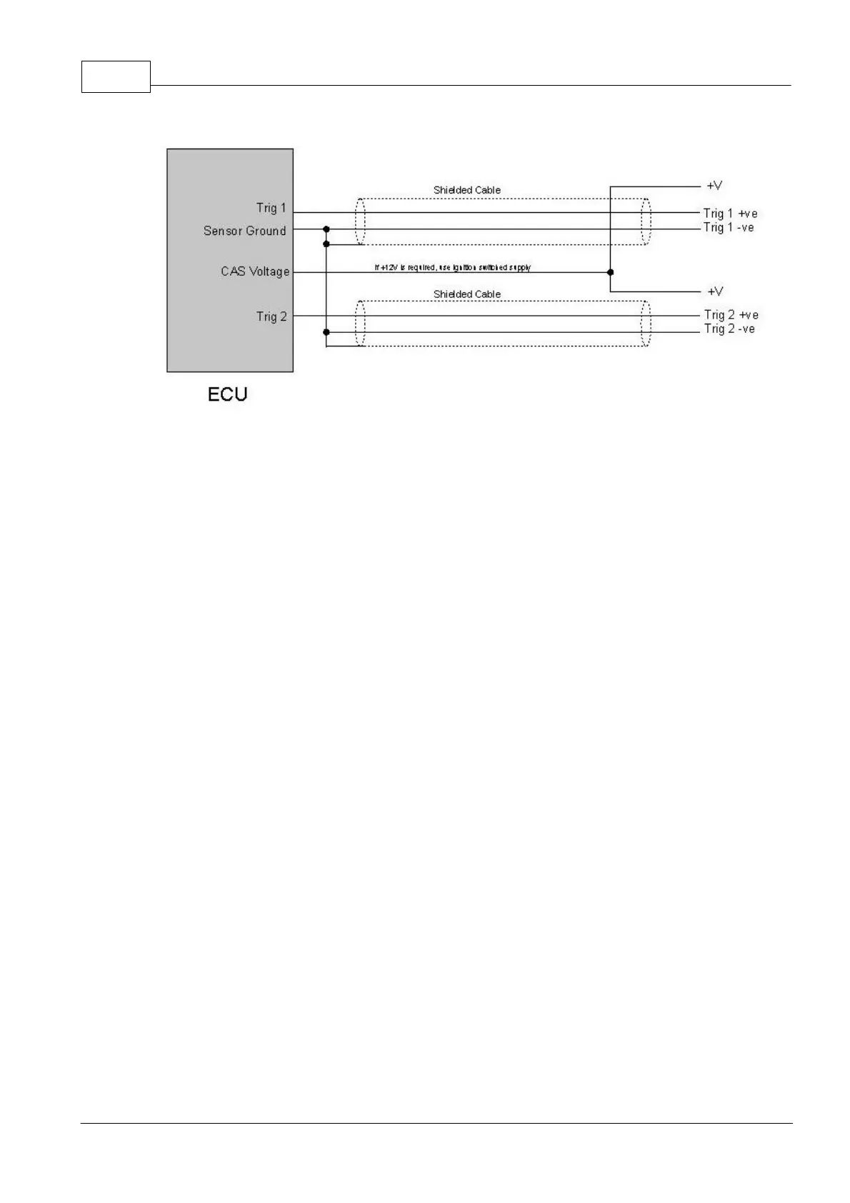
Optical/Hall/Proximity Sensor Wiring
7.2 MAP Sensor
A MAP sensor will be required in all cases except for naturally aspirated engines with very
aggressive camshaft profiles. The MAP fluctuations caused by large amounts of overlap
result in a very unstable MAP reading especially at idle. Also note that multi-butterfly
engines often give a poor vacuum signal. In these cases, it is best to use the throttle
position (rather than MAP) to indicate the engine load. In all cases where forced induction is
used, a MAP sensor is required.
Storm ECU's have an internal MAP sensor. If a higher pressure is required than that of the
internal MAP sensor, an external MAP sensor can be wired to an Analogue Volt input. To
use the internal MAP sensor connect the MAP pressure hose to the barbed fitting on the
ECU's end plate.
Xtreme ECU's require the wiring and mounting of an external MAP sensor (if a MAP sensor
is to be used).
The MAP sensor must be connected to the inlet manifold via a suitable length of 3mm
(minimum size) vacuum hose. The take off point must be between the engine and throttle
plate so that the MAP sensor registers vacuum (as well as pressure on turbo applications).
The take off point must be from a common chamber that is connected to all cylinders rather
than off a single intake runner. The fuel pressure regulator's pressure signal is usually a
good take-off point. However, do not be tempted to share the MAP sensor vacuum hose
with other devices such as a boost gauge or in particular a blow off valve.