Output Wiring 33
© 2009 Link
Inj 1 = Pri 1
Inj 2 = Pri 2
Inj 3 = Pri 3
Inj 4 = Pri 4
Inj 5 = Sec 1
Inj 6 = Sec 2
Inj 7 = Sec 3
Inj 8 = Sec 4
Inj 1 = Pri 1
Inj 2 = Pri 2
Inj 3 = Pri 3
Inj 4 = Pri 4
Inj 5 = Pri 5
Inj 7 = Sec Group 1
Inj 8 = Sec Group 2
Inj 1 = Pri 1
Inj 2 = Pri 2
Inj 3 = Pri 3
Inj 4 = Pri 4
Inj 5 = Pri 5
Inj 6 = Pri 6
Inj 7 = Sec Group 1
Inj 8 = Sec Group 2
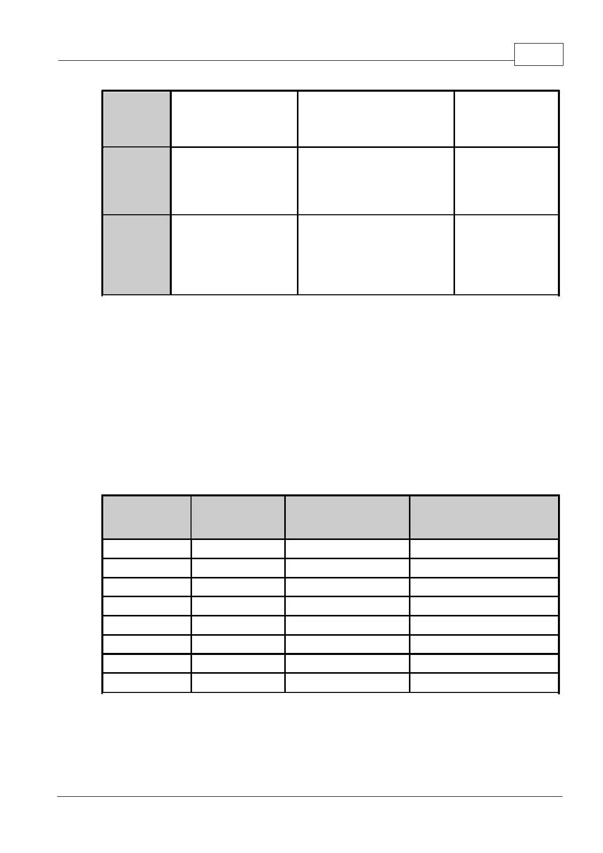
Full primary and secondary sequential injection can only be achieved on engines with four
cylinders or less. Wire injectors as shown in the preceding table. On engines with 5 or 6
cylinders the primary injectors will be fired sequentially and secondary injectors fired in
group mode. Engines with 8 or more cylinders must use Group Staged Injection.
Set the 'Injection Mode' to 'Sequential/Staged' when using this configuration.
8.2 Ignition Drives
Note: For information on wiring Ignition Outputs as additional Auxiliary Outputs, refer to the
section on wiring Auxiliary Outputs.
G4 ECU's have up to 8 independent ignition drives which can be used in a wide range of
configurations from a basic distributor set-up through to more complex multi-coil
arrangements. G4 ECU's support the ignition configurations shown in table below.
Wasted Spark (1
Dual Post Coil per
two Cylinders)
Direct Spark (1 Coil per
Cylinder)
Available Ignition Combinations (* Xtreme ECU Only)
8.2.1 Igniter Requirements
An igniter acts as an interface between the ECU and the ignition coil(s). The Igniter is used
to drive the coil(s) by supplying a ground for the coils negative terminal. Wiring of an igniter