Output Wiring 43
© 2009 Link
Wiring for two-terminal ISC solenoid on Ignition Output
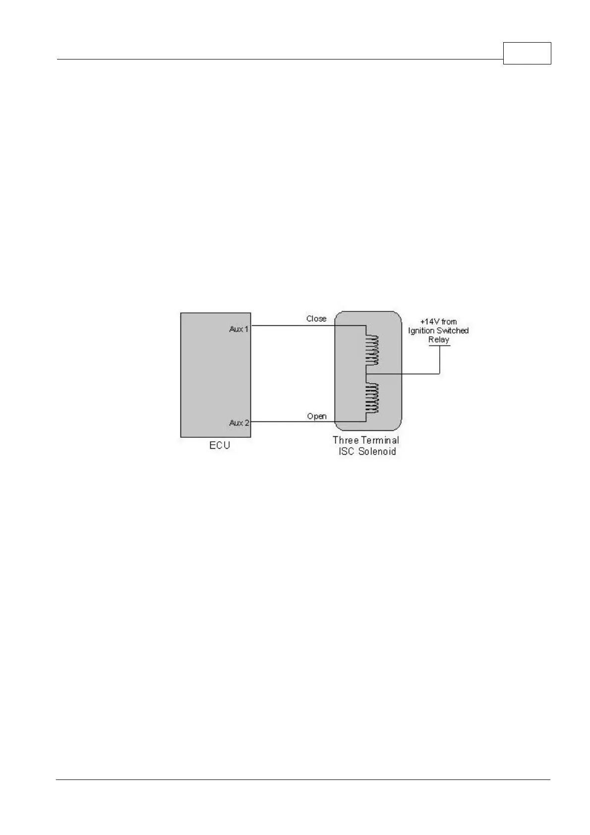
8.4.2 Three Terminal ISC Solenoid
A Three Terminal ISC Solenoid must be wired to Aux 1 and Aux 2. Aux 1 is ISC Close, Aux
2 is ISC Open.
Three terminal ISC solenoids needs one Auxiliary Output to open the solenoid and another
Auxiliary Output to close it.
Use an ohmmeter to find the common terminal (usually the centre). Figure 8.14 shows the
schematic. Next measure the resistance between the common and remaining two terminals.
This should be greater than 10 ohms. Apply +12V to the common terminal of the solenoid.
Ground one of the other terminals. If this terminal causes the valve to open, connect it to an
Auxiliary Output 2 and note that this output should be configured as 'ISC Solenoid'. If the
valve closes, connect the terminal to Auxiliary Output 1 and note that this output should be
configured as 'ISC Solenoid Slave'.
Three terminal ISC Solenoid Wiring
8.4.3 Four Terminal ISC Stepper Motor
An ISC Stepper Motor must be wired to Aux 5, Aux 6, Aux 7 and Aux 8.
When using an ISC Stepper, the ECUs power supply should be wired for ECU Hold Power
as shown in Figure 6.2. This will allow the ECUs Hold Power function to be taken advantage
of. Using ECU Hold Power allows the ECU to reset the stepper motor after key off. This
avoids extended cranking periods caused by resetting the stepper at key on.
The diagram below shows a schematic of a four-terminal stepper motor. Note that there are
two coils. Use an ohmmeter to pair the terminals with a common coil. Aux 5 and 6 must be
connected to the terminals for one coil, while Aux 7 and 8 must be connected to the
terminals for the other coil. If it is found that the stepper motor runs in the opposite direction
to that expected, reverse the wiring to Aux 5 and Aux 6.