Input Signal Wiring 29
© 2009 Link
in PCLink Tuning Software.
VVT Cam Position Input
Continuously Variable Valve Timing (CVVT, VVT, VVTi, AVCS) Cam Position digital inputs
can only be connected to Digital Inputs 1 to 4.
Reluctor or Optical/Hall sensors can be used to measure camshaft position on engines
equipped with VVT systems. VVT position sensors should be wired to digital Inputs in the
same manner as Trigger Sensors. This includes the use of Sensor ground and shielded
cables. Shielded cable for Digital Input wiring is not included in the standard loom but can
be purchased from your Link dealer. Not using shielded cable can result in cam shaft
position measurement errors.
For engine specific information on the wiring of triggers and VVT position sensors refer to
your Link dealer or www.LinkECU.com.
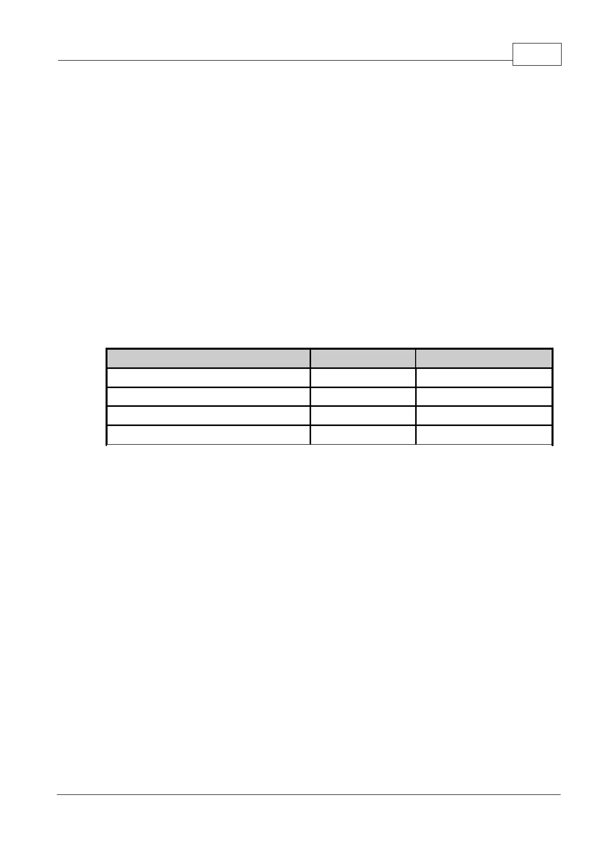
Although not absolutely necessary, it is recommended to ease configuration that cam
position signals are wired to the same number Digital Input channel as the corresponding
solenoid control Auxiliary Output (refer following table). For compatibility, the following use
of Digital Inputs and Auxiliary outputs is recommended for VVT wiring. Note that in practice
any Digital Input/Auxiliary Output combination can be used.
In cases where the same camshaft position signal is used to measure camshaft timing as
well as provide sync (firing order position) information, this sensor will usually be wired to
Trigger 2.
8 Output Wiring
The following sections describe wiring of output devices to G4 ECU's.
8.1 Fuel Injector Drives
Note: For information on wiring Injection Outputs as additional Auxiliary Outputs, refer to the
section on wiring Auxiliary Outputs.
The injector drives on a G4 ECUs work by supplying an EARTH to turn the injectors on. A
switched (key ON) 12V must be supplied to the other terminal of the injector. The polarity
of the injector is not important. Note that injectors should be powered from the same supply
as the ECU. This ensures the ECU has accurate measurement of injector voltage for
calculating injector dead time.
DO NOT connect +12V directly to any of the injector drives
Injectors are commonly available as either high impedance or low impedance. To determine
injector impedance: With the injector unplugged, use an ohmmeter to measure the