G4 Wiring and Installation Manual20
© 2009 Link
The braided shield in both cables MUST not be grounded at the sensor end. If the sensor
has its own shielded wire connection, make sure this does not connect directly to the engine
block.
There are a large number of triggering variants used by different engine manufacturers.
The important differences are the type of sensors used, the number of pulses sent from the
sensors during an engine cycle and the timing of the pulses in relation to the engine cycle.
There are two main types of sensors that are commonly used. It is important that the sensor
type is known, as the wiring for each type is completely different.
7.1.1 Reluctor/Magnetic Sensors
Reluctor/Magnetic sensors have a toothed trigger wheel that passes across the face of the
sensor. The movement of the teeth past the sensor generates a voltage in the sensors
winding. These sensors usually have only two wires as the sensor itself generates a
voltage. One wire is the sensor ground while the other is the signal output. Some reluctor
sensors have a second ground to sheild their enclosure and therefore have three wires.
These sensors are often identified by sharp tooth profiles.
The polarity of the reluctor sensors two wires is very important and
must be correct. Wiring of sensors incorrectly could result in erratic
running and possibly engine damage
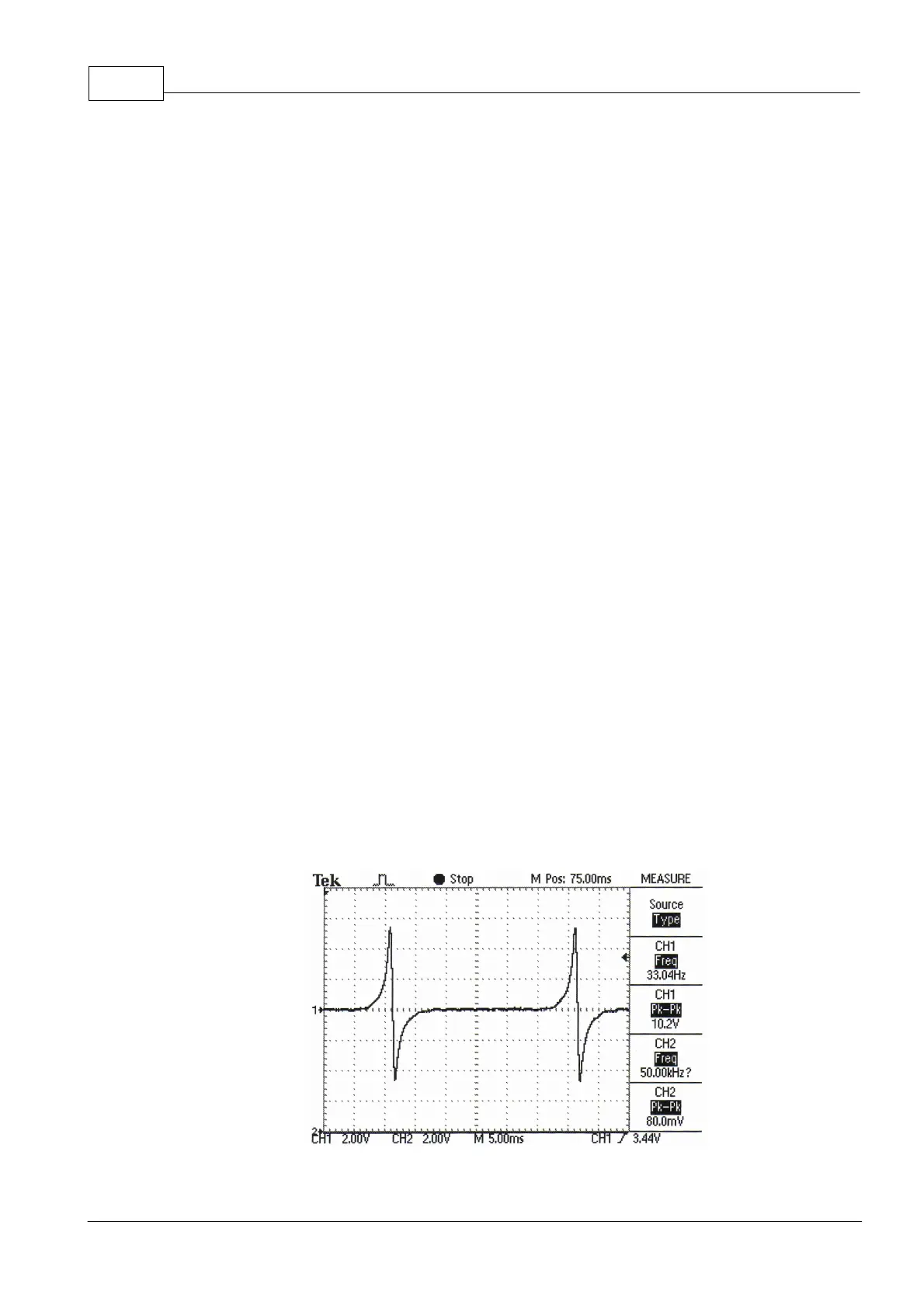
Reluctor sensors MUST be wired so that the ECU sees a positive voltage as the tooth
approaches the sensor and a negative voltage as the tooth leaves the sensor. An
oscilloscope is usually required to determine correct reluctor polarity.
Correct Reluctor Polarity