Input Signal Wiring 21
© 2009 Link
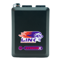
INCORRECT Reluctor Polarity
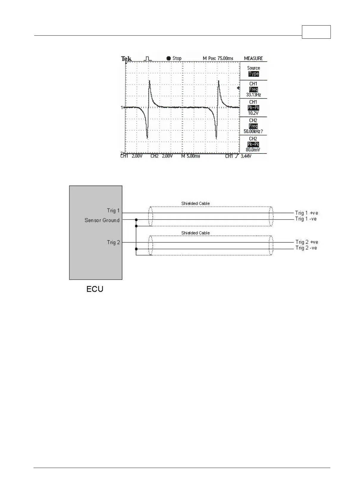
Reluctor Sensor Wiring
7.1.2 Hall/Optical/Proximity Sensors
Optical, Hall effect and Proximity sensors typically use a trigger wheel with slots or tabs cut
out to generate pulses. These sensors require a power supply and typically have three
wires.
The +8V Supply offers a regulated 8V for optical or hall sensors. These wires are not used
for reluctor sensors. Note: many hall sensors will not tolerate 12V and require a 5V or 8V
regulated supply.
Most optical or hall sensors will require the 'Trigger Pull-up Resisters' to be turned on in.
This is done in the 'Trigger 1' and 'Trigger 2' menus in PCLink Tuning Software.