Output Wiring 35
© 2009 Link
should be correctly set to avoid damage to coils and igniters and also ensure adequate
spark energy. It is not true that increased dwell time will always result in increased spark
energy.
Use only coils designed for high-energy transistor/inductive ignition systems. The coils
primary resistance should typically be between 0.4 O and 1.0 O. This applies to both single
and dual post coils in distributed and multi coil applications.
8.2.3 Ignition System Wiring
The following guidelines should be considered when wiring ignition systems:
· Unsuppressed H.T. leads act as aerials and radiate very powerful interference signals.
ALL applications must use suppressed HT leads
, preferably resistance type rather
than spiral wound or inductive. Typically these vary from 1000 ohms to 5000 ohms
depending on lead length. NEVER use plain wire leads.
· ALL applications must also employ a suppressor capacitor (0.5 - 3uF) connected
directly between the ignition coil(s) POSITIVE terminal and ground. Most points
condensers are suitable. Multiple coils can share a single suppressor. ‘V’ and boxer
engines with multiple coils must have a suppressor on each bank.
· Isolate the ignition system as much as possible from other sensitive devices, especially
the ECU. Do not run non-ignition related wiring close to igniters, coils or HT leads
wherever possible. Maintain maximum distance from radio transmitters and coaxial
cables etc.
· Always use resistor spark plugs. These can be checked by measuring the resistance
between the top of the spark plug and the centre electrode. On a resistor plug the
resistance will be several thousand ohms.
· If insufficient ignition energy is causing a high-power misfire (especially on turbo/super
charged engines), it may be necessary to reduce the spark plug gap. Gaps as small
as 0.5mm (.020') may be necessary. This also reduces the amount of radiated
electrical noise due to the lower firing voltage.
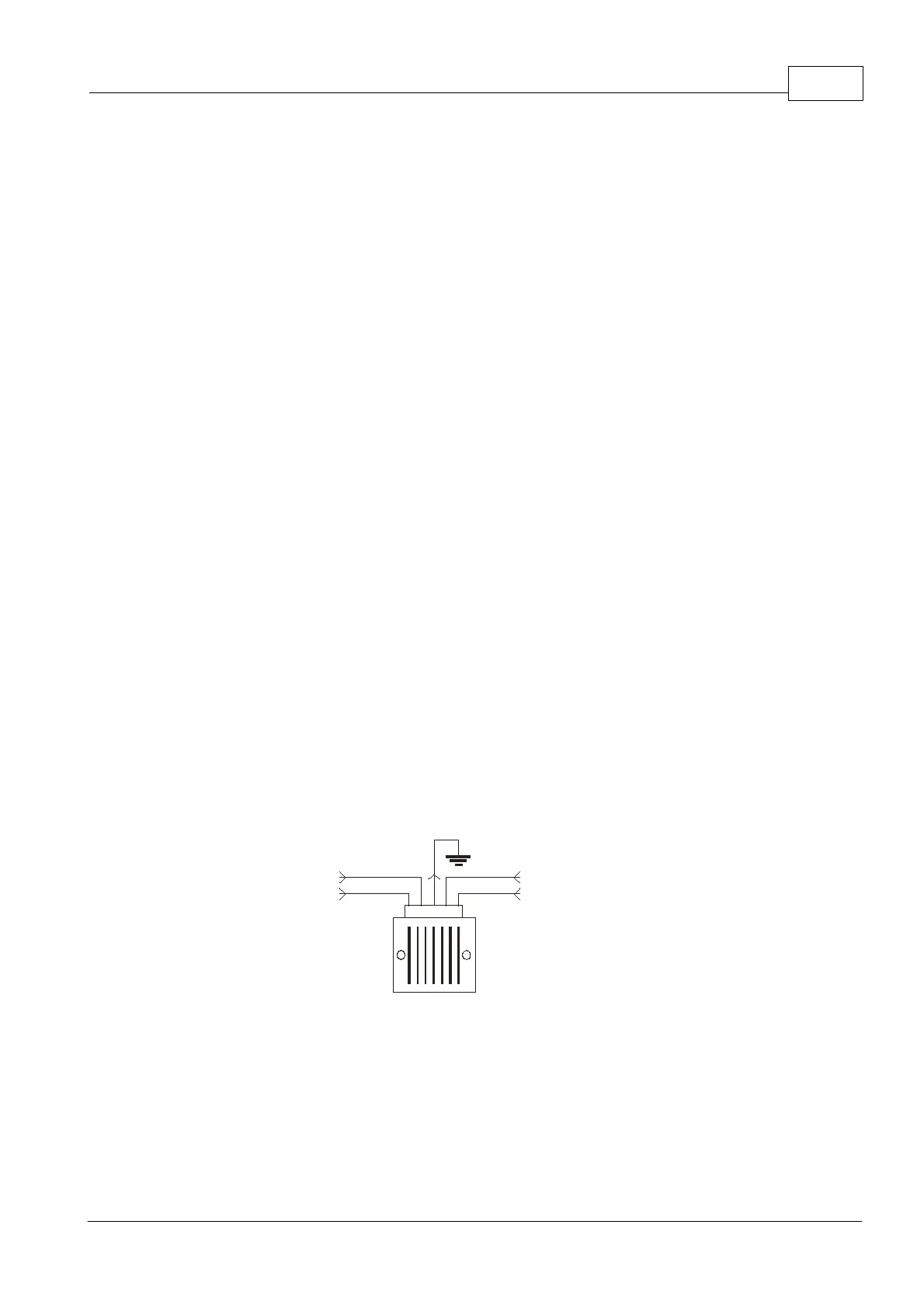
· Keep the input wiring to the igniter (from the ECU) separate from the output wiring of
the igniter (to the coils) as shown below.
Igniter
Signals from ECU
Outputs to Coils
Note:
- Separate Sensitive Signal wires from Coil Wires
- Ground ignitor to engine block (keep wiring short)
Separation of igniter input and output wiring
8.2.4 Distributor Ignition
A distributor rotates at half the crankshaft speed and routes the high voltage generated by
the coil to the intended spark plug via a rotor and HT wiring. A distributed engine requires
one ignition drive and a single channel igniter. Use Ignition Drive 1 to switch the igniter.
Because the rotor will only point to each post on the distributor cap for a short amount of